
Services · Materials Testing · Fatigue and Fracture Toughness
Fatigue and Fracture Toughness Testing per ASTM E1820, E399, E647 and E466
S-N and strain-controlled fatigue, fatigue crack growth, KIc and J-integral, pre-cracked and tested in-house on 50, 250 and 1,000 kN servo-hydraulic frames, reported under NABL NABLT0726MH18640.
Request a Quote
What this service covers
TCR Engineering, a NABL ISO/IEC 17025:2017 laboratory (NABLT0726MH18640) in Navi Mumbai, runs fatigue and fracture toughness testing on metals: S-N fatigue per ASTM E466, strain-controlled fatigue per ASTM E606, crack growth per ASTM E647, KIc per ASTM E399 and J-integral per ASTM E1820, with reports accepted in 90+ economies under the ILAC MRA.
- On this page: fatigue life, crack growth and fracture toughness of metals, rail and rail-weld fatigue, and fatigue of rebar couplers, grout, strand and springs.
- CTOD testing of welds, plate and pipe, including sub-zero and H2S pre-charged CTOD, has its own page: CTOD testing per BS 7448, ISO 12135 and ASTM E1820.
- Manhole covers and gully tops to BS EN 124, IS 1726 and IS 12592 have their own page: manhole cover and gully top testing.
- The laboratory: servo-hydraulic frames rated 50 kN, 250 kN and 1,000 kN, 0.01 to 40 Hz, -65 °C to 1,100 °C.
- Aerospace: NADCAP AC7101 Materials Testing accredited 2026, for aerospace verification testing.
What Each Test Tells You
Fatigue testing tells you how long a part lasts under cyclic load. Fracture toughness testing tells you how large a crack it can carry before it breaks. Designers use the first to set a service life; integrity engineers use the second to decide whether a flaw found in service can stay.
- S-N fatigue (high-cycle): stress against cycles to failure under force control, for components, fasteners and welded joints.
- Low-cycle fatigue: strain-controlled cycling, for parts that yield locally on every cycle.
- Fatigue crack growth rate: how far a crack grows per cycle (da/dN against ΔK), the input to a remaining-life calculation.
- Plane-strain fracture toughness (KIc): the toughness of a thick section that fractures without much yielding.
- J-integral: the toughness of a material that yields before it fractures.
- CTOD: the toughness measure weld specifications such as API 1104 Annex A use, on the CTOD testing page.
- Charpy transition curve: impact energy across a range of temperatures, to place the ductile-to-brittle transition, on the mechanical testing page.
Methods, Standards and NABL Scope
The table lists each fatigue and fracture method the laboratory runs, the standard it is reported to, and whether that method is on NABL certificate NABLT0726MH18640. Where a client specification calls for a different governing document, the report states the decision rule applied.
| Method, specimen range and NABL scope | Standard |
|---|---|
| Force-controlled axial fatigue (S-N, HCF) Components, fasteners, welded joints; ambient to 1,100 °C NABL scope: on |
ASTM E466; IS 5074 |
| Strain-controlled fatigue (LCF) Low-cycle fatigue NABL scope: on |
ASTM E606; ISO 12106 |
| Fatigue crack growth rate Metallic materials, including rail steels per EN 13674; -65 °C to 1,100 °C NABL scope: on |
ASTM E647; ISO 12108 |
| Plane-strain fracture toughness (KIc) 7.5 mm to 90 mm thick; square-section B x B from 75 mm to 90 mm NABL scope: on |
ASTM E399; ISO 12737; ASTM B645 (aluminium) |
| J-integral (JIc) -65 °C to 1,100 °C NABL scope: on |
ASTM E1820; BS 7448; ISO 12135 |
| CTOD Including H2S pre-charging in NACE TM0177 Solution A; see CTOD testing NABL scope: on |
BS 7448; ISO 15653; ISO 12135; BS 8571; ASTM E1820 |
| Creep-fatigue interaction High-temperature cyclic duty NABL scope: outside |
ASTM E2714 |
| Rail and rail butt-weld fatigue Four-point bending, 1,000 mm span, on the 1,000 kN frame NABL scope: IRS:T-19 and BS EN 14587 on; IRS:T-29 and ISO 14587 outside |
IRS:T-19; BS EN 14587-2; IRS:T-29; ISO 14587 |
| Rebar coupler fatigue Bars 8 mm to 40 mm; LCF and HCF NABL scope: on |
IS 16172; ASTM A1034; IS 16651; ISO 15630; ISO 15835-2 |
| Grout fatigue Grouts for mechanical splices NABL scope: outside |
CEB-FIP Model Code 1990/2010 |
| High-tensile strand fatigue 2 million cycles at the upper load specified by ISO 15630-3 / EN 10138 NABL scope: outside |
IS 14268; ASTM A416; EN 10138-3; ISO 15630-3 |
| Helical spring static and fatigue Static load, spring rate, fatigue NABL scope: outside |
RDSO standards |
| Manhole and gully top fatigue See manhole cover and gully top testing NABL scope: outside |
BS EN 124-5 |
How an ASTM E466 Fatigue Job Is Set Up
An ASTM E466 job starts from the client's specimen drawing and load case. TCR machines the specimens to the drawing, cycles them under force control at constant amplitude at room temperature, usually tension to tension from zero, and stops at fracture or at the cut-off the client sets. The table is a worked set-up for steel.
| Item | Set-up |
|---|---|
| Loading | Force control, constant amplitude, R ≈ 0 (zero to maximum, tension to tension) |
| Frequency | About 5 Hz, or the highest the specimen allows |
| End point | Fracture, or the specified cut-off, for example 75,000 cycles |
| Load | As specified by the client |
| Specimen | Cylindrical reduced section: gauge diameter 6.35 ± 0.05 mm, gauge length 25.0 mm, transition radius 50.8 mm, grip diameter 12.7 mm, grip length 30 mm, overall length 120.36 mm |
| Surface | Gauge section polished longitudinally to Ra ≤ 0.2 µm |
| Frame | On the 31.67 mm² section, 700 to 900 MPa peak stress is a peak force of 22.2 to 28.5 kN, well inside the 50 kN frame |
Send the specimen drawing, the material and its condition, the stress or force levels, the stress ratio, the cut-off and the number of specimens at each level. Specimens are machined to the drawing in TCR's own machine shop.
Plane-Strain Fracture Toughness to ASTM E399
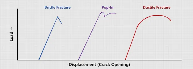
ASTM E399 measures KIc on a pre-cracked compact tension, C(T), specimen. TCR machines the specimen, grows the fatigue pre-crack, loads it to fracture and reads the result off the load against displacement record. The value is KIc only when every validity check of the standard is met; otherwise the report gives the conditional value, KQ.
- Specimen: compact tension, C(T), at least 7.5 mm thick, machined in-house.
- Pre-crack: grown in fatigue, tension to tension, before the test.
- Validity: the size and crack-front checks of ASTM E399, stated on the report.
- Thin plate: where the material is too thin for a valid KIc, as with Ti-6Al-4V ELI plate machined below 10 mm, TCR reports KQ per ASTM E399.
The Fatigue Test Laboratory
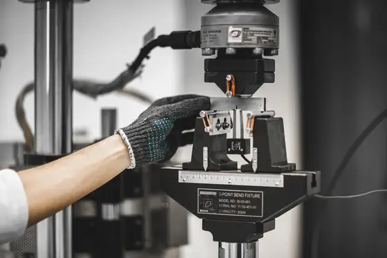
The Fatigue Test Laboratory in Navi Mumbai is built around servo-hydraulic dynamic universal testing machines rated 50 kN, 250 kN and 1,000 kN. They run from 0.01 to 40 Hz and, with the environmental chamber and two cold chambers, test from -65 °C to 1,100 °C. Specimens are machined and pre-cracked in-house.
- Specimen sizes: KIc, JIc, CTOD and fatigue crack growth specimens 7.5 mm to 90 mm thick, with a square-section B x B specimen from 75 mm to 90 mm; bend spans from 55 mm to 1,600 mm.
- Strain rate: high strain rate testing to 300 mm/s on the 50 kN frame and 100 mm/s on the 250 kN frame; slow strain rate to 10−7 mm/s.
- Loading: repeated fixed loads or simulated service loads, applied through linear and hydraulic actuators.
- Comparison testing: fatigue life of OEM and alternate-source parts on the same frame, to demonstrate equivalence.
Programmes Delivered
Fatigue and fracture programmes at TCR come mainly from railways, which need rail, weld and rail-steel fatigue to RDSO and EN standards, and from aerospace and defence, which need verification testing under NADCAP and long-running fracture toughness contracts. Pipeline CTOD and ECA programmes are listed on the CTOD testing page.
-
Rail-Track Fatigue Crack Growth
Fatigue crack growth testing of rail steels per EN 13674 for Jindal Steel & Power, and rail fatigue per IRS:T-29 for RDSO-governed programmes.
-
Fracture-Toughness Programmes
Verification testing for HAL, MTAR Technologies and Vikram Sarabhai Space Centre, with aerospace work under NADCAP AC7101, and fracture-toughness programmes for the Navy and defence.
-
Long-Term Contracts
Long-term contracts from NMRL and DMRL for fracture toughness, LCF and HCF fatigue and S-N curves including KIc and JIc, with approvals from CQAE, DRDO.
Rail and Rail-Weld Fatigue
Rail joints are fatigue tested as lengths of welded rail. The joint is mounted in four-point bending over a 1,000 mm span on the 1,000 kN dynamic frame and cycled at 8.33 to 9.0 Hz to 5 million cycles, with three specimens drawn from eleven for statistical validation.
- Set-up. A welded rail joint, flash butt or another butt-welding process, mounted in the four-point bend fixture.
- Loading. Repeated vertical load that reproduces the stress pattern of passing trains.
- Monitoring. Strain, displacement and crack growth recorded through the test, with strain gauges or non-destructive methods where specified.
- End point. The cycle count, or the failure criterion the standard defines: a crack, or a change in strain or displacement.
- Result. Fatigue life and behaviour reported against the governing standard.
Standards: RDSO IRS:T-19 and IRS:T-29, BS EN 14587 Parts 1 and 2, ISO 14587 and BS EN 13674-1. Track fastenings are tested to IRS:T-31 (elastic rail clips, MK-V type) and IRS:T-44 (insulating liners, RT-3506, GFN-66/HVN). Rail work for Indian Railways, metro systems and the Mumbai-Ahmedabad High Speed Rail is described on the railways page.
Couplers, Grout, Strand and Springs
The same frames test construction and rail products whose failure mode is fatigue. Rebar couplers are tested statically and in cyclic fatigue, grout for mechanical splices to the CEB-FIP Model Code, high-tensile strand for bridge and rail cable systems, and helical springs to RDSO standards.
- Rebar couplers: static tensile, slip, cyclic tensile, fatigue, LCF and HCF on bars of 8 mm to 40 mm, including the 100-cycle and 2 million-cycle tests of IS 16172; detail on the rebar coupler page.
- Grout: fatigue of grouts for mechanical splices, to the CEB-FIP Model Code 1990 / 2010.
- High-tensile strand: 2 million-cycle fatigue at the upper load the governing standard (ISO 15630-3 / EN 10138) specifies, for prestressed bridge and high-speed-rail cable systems.
- Helical springs: static load, load against displacement (spring rate) and fatigue.
- Composite manhole and gully tops: fatigue to BS EN 124-5, on their own page.
Related services and industries
Fracture toughness rarely travels alone: welds need CTOD, high-temperature plant pairs fatigue with creep, and every fracture number feeds an Engineering Critical Assessment under the asset integrity pillar.
Related insights
2 published insights on this site bear directly on Fatigue and Fracture Toughness. They are below; the full index carries all 165 Materials Testing insights.
-
Fatigue, CTOD and Fracture Toughness Testing
TCR has state of the art servo hydraulic universal testing machines
-
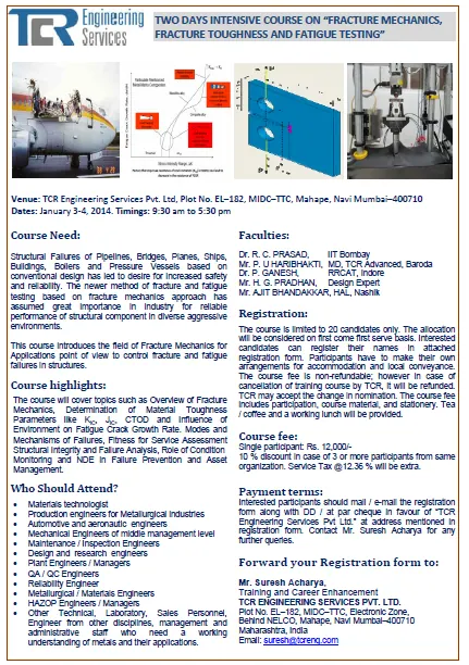
Course on "Fracture Mechanics, Fracture Toughness and Fatigue Testing"
The course is designed to blend theory and practical aspect of the subject.
Frequently asked questions
Which standards govern fatigue and fracture toughness testing at TCR Engineering?
Force-controlled axial fatigue per ASTM E466, strain-controlled fatigue per ASTM E606 and ISO 12106, fatigue crack growth per ASTM E647 and ISO 12108, plane-strain KIc per ASTM E399 and J-integral per ASTM E1820, with rail fatigue per IRS:T-19, IRS:T-29 and BS EN 14587. CTOD has its own page.
What temperature range can TCR test at?
Fracture toughness and fatigue crack growth run from -65 °C to 1,100 °C, on specimens 7.5 mm to 90 mm thick pre-cracked in-house. Uniaxial fatigue runs from ambient to 1,100 °C. Sub-zero CTOD is described on the CTOD testing page.
Where is CTOD testing covered now?
On the CTOD testing page, which covers BS 7448, ISO 15653, ISO 12135, BS 8571 and ASTM E1820, sub-zero and H2S pre-charged CTOD, and the pipe mill, marine and defence programmes TCR has delivered.
Are TCR's fracture toughness reports accepted outside India?
Yes. TCR Engineering's NABL ISO/IEC 17025:2017 accreditation (NABLT0726MH18640) sits under the ILAC MRA, so reports are accepted in 90+ economies by reciprocal bodies including A2LA, UKAS, DAkkS and Cofrac. Samples are received from 15+ countries.
Does TCR run ASTM E561 R-curve tests?
No. TCR does not have the set-up for ASTM E561 R-curve testing on middle-crack tension, M(T), specimens and does not offer it. Fracture toughness work here covers KIc to ASTM E399, J-integral to ASTM E1820, CTOD and fatigue crack growth to ASTM E647.
Which industries use TCR's fatigue and fracture toughness testing?
Railways (fatigue crack growth per EN 13674 for Jindal Steel & Power and rail fatigue per IRS:T-29 for RDSO-governed work), aerospace and defence (NADCAP AC7101 Materials Testing accredited 2026; programmes for HAL, MTAR Technologies, Vikram Sarabhai Space Centre and the Navy), construction (rebar couplers and strand), pipelines, marine and offshore, and power generation.