
Services · Asset Integrity and Engineering Consulting
Boiler and Heater Tube Failure Analysis
A tube failure is a symptom. The mechanism is what decides whether the unit comes back up or fails again in the same header.
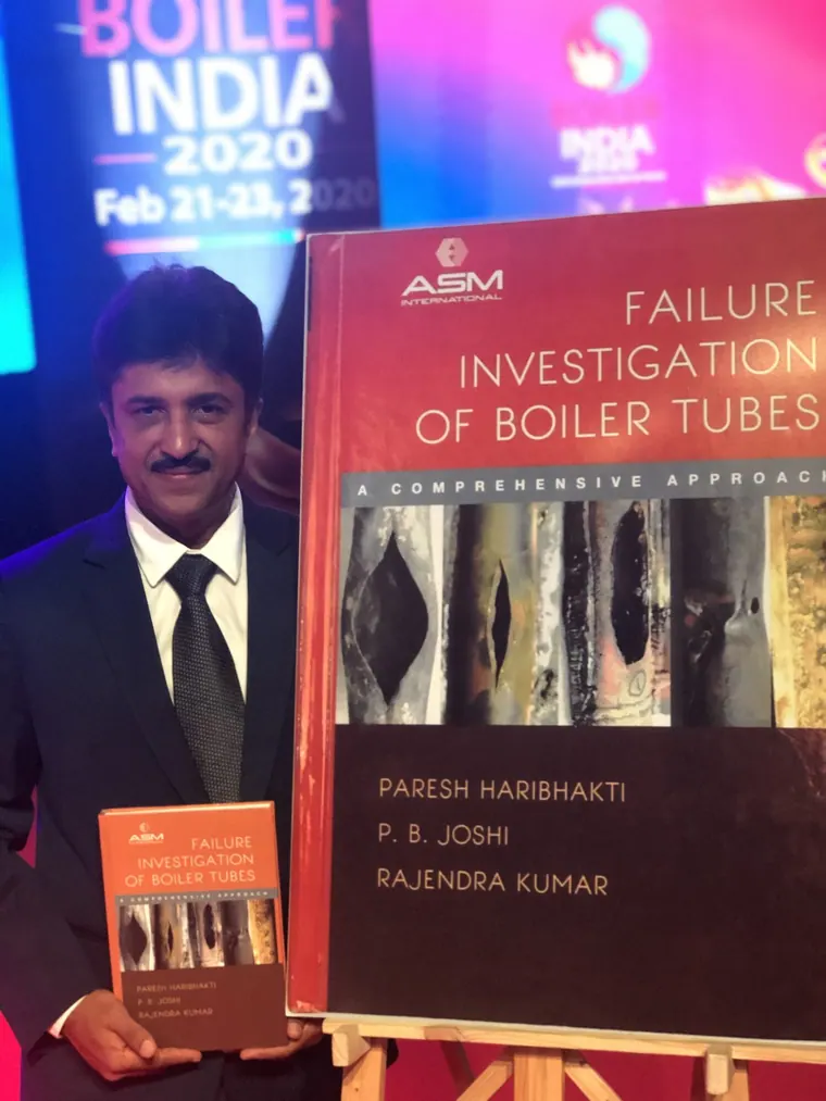
Paresh Haribhakti, Managing Director of TCR Advanced Engineering, is a co-author of Failure Investigation of Boiler Tubes: A Comprehensive Approach, published by ASM International, Ohio, in 2018.
Request a QuoteOverview
TCR Engineering Services Pvt. Ltd., a NABL ISO/IEC 17025:2017 accredited laboratory in Navi Mumbai and an IBR Well-Known Material Testing Laboratory, investigates boiler, superheater, reheater, economiser, waterwall and fired heater tube failures. The practice rests on 1,500+ documented tube failure investigations and 400+ boiler remaining-life assessments.
The Mechanism Decides the Repair
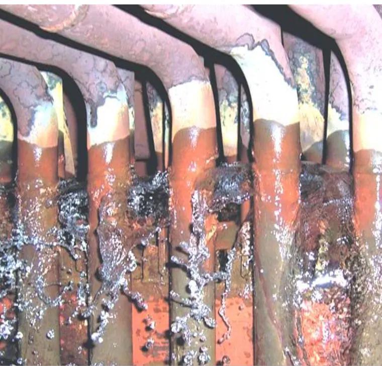
Every boiler tube failure looks broadly the same from the walkway: a hole, a split, a burst. The mechanisms behind them are entirely different, and so are the corrective actions. Replacing the tube without naming the mechanism buys the interval to the next failure and nothing more.
- Short-term overheating gives a thin-lipped fish-mouth rupture with heavy plastic deformation and a transformed microstructure. The cause is a loss of flow, not a loss of material.
- Long-term overheating and creep gives a thick-lipped rupture, longitudinal cracking, external oxide scale and a microstructure that has spheroidised, coarsened its carbides and, at the end, cavitated on the grain boundaries.
- Waterside corrosion fatigue gives transverse, oxide-filled cracks initiating on the inside surface at points of restraint, and it is a cycling and chemistry problem together.
- Caustic gouging and acid phosphate corrosion give irregular internal wall loss under a deposit, and both are settled by deposit analysis, not by looking at the metal.
- Hydrogen damage gives a thick-lipped, window-type failure with decarburisation and intergranular microfissuring, and the surrounding tubes are usually affected before they leak.
- Fireside and coal-ash corrosion gives external wastage under a molten or semi-molten deposit, with a characteristic layered scale.
- Erosion from fly ash, soot blowers, falling slag or coal particles gives directional external thinning with a polished or scalloped surface.
- Dissimilar metal weld failure gives a fracture at or just off the ferritic side of the transition, and it is a design and thermal-expansion problem, not a welding-quality problem.
- Graphitisation, thermal fatigue, stress corrosion cracking and maintenance damage complete the set, and each has its own signature.
TCR reports against the full named taxonomy rather than against a general description, because a plant that is told "overheating" cannot act, and a plant that is told "long-term overheating with an estimated tube metal temperature above design and a spheroidised microstructure" can.
Reading Tube Metal Temperature from the Tube Itself
The most useful number in a superheater or reheater investigation is rarely on any instrument. It is the temperature the metal actually saw, and the tube carries two independent records of it.
| Evidence | What is measured | What it establishes |
|---|---|---|
| Steam-side oxide scale thickness | Scale thickness measured metallographically on a transverse section | An estimate of the accumulated tube metal temperature history, read through the standard oxide-growth correlations |
| Microstructural degradation stage | Pearlite spheroidisation, carbide coarsening, carbide precipitation at grain boundaries, creep cavitation | How far through its creep life the material has run, independently of any temperature record |
| Hardness | Hardness traverse across the wall | Softening consistent with the degradation stage, and the presence of any unintended transformed layer |
| Dimensional change | Outside diameter swell and wall thinning against nominal | Creep strain accumulated, and whether the tube was already at the replacement criterion |
| Deposit and scale chemistry | Internal deposit and external scale analysed by EDS and wet chemistry | Whether the driver was water chemistry, fuel chemistry or both |
Where the failure raises a question about the rest of the circuit, the tube evidence feeds directly into a remaining life assessment. TCR has completed 400+ boiler remaining-life assessments and holds recognition as a Well-Known Remaining Life Assessment Organisation from the Central Boilers Board.
What to Send, and How to Cut It
A tube failure investigation is only as good as the section that reaches the laboratory. The single most common avoidable problem is a sample cut too close to the damage, which removes the material the comparison depends on.
- Length: at least 300 mm either side of the failure where the outage allows it, so that undamaged parent material from the same tube is available as the control.
- Orientation: mark the fireside, the crown and the flow direction on the tube before it is cut. Once the section is off the wall that information cannot be recovered.
- Cutting: cut cold where possible. A torch cut through the region of interest destroys the microstructure that the investigation is there to read.
- Deposits: do not clean, flush or wire-brush the internal surface. The deposit is evidence, and in a caustic gouging or acid phosphate case it is the primary evidence.
- Identification: the tube specification, the location in the circuit, the elevation, the hours in service and the operating conditions, including any recent excursion.
Where the unit is down and a decision is needed inside the outage, say so at the point of sampling. The sequence is ordered to give the operational answer first and the full documented report after.
The Fleet Question, Answered Without Cutting
One failed tube raises the question of every tube on the same header and every unit of the same design. Cutting the rest out to answer it is not an option, which is what in-situ metallographic replication is for.
- In-situ metallography to ASTM E1351: the microstructure is read in place, on the live component, with no cutting and no sample removal. TCR has taken more than 100,000 in-situ replicas and fields 12 in-situ metallographic teams across the group.
- Hardness in place: portable hardness on the same locations, so degradation is scored against two independent measurements.
- Replica interpretation against an archive: a replica is only as good as the reference base it is read against, and TCR reads them against its own.
- Where it leads: a boiler audit, a remaining life assessment under IBR Regulation 391A, or a knowledge-based risk assessment that ranks the circuit rather than the single tube.
Adani Power Mundra had its 4,620 MW boiler and piping fleet assessed this way, at 20 days per unit. Reliance Jamnagar had 1,200 in-situ replicas taken and interpreted in 15 days inside a live turnaround.
Related services and industries
The book on boiler tube failure, written here
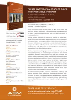
Paresh Haribhakti, Managing Director of TCR Advanced Engineering, wrote Failure Investigation of Boiler Tubes: A Comprehensive Approach with P.B. Joshi and Rajendra Kumar. ASM International, the American materials society, published it on 1 December 2018. The investigations behind this service page and the investigations behind that book are the same body of work.

The book is a comprehensive treatment of boiler tube failure: the seventeen recognised damage mechanisms, from short-term and long-term overheating through waterside and fireside corrosion, caustic gouging, hydrogen damage, stress corrosion cracking, creep, corrosion fatigue, erosion and graphitisation; the field and laboratory evidence that identifies each one, including in-situ metallography, oxide-scale measurement, dimensional survey, replication and fractography; and the corrective and preventive actions that follow from the diagnosis. It draws on more than 1,500 boiler tube failure investigations carried out by the TCR group.
ASM's own description: “Coal-fired power plants rely on a network of boiler tubes that would stretch several kilometers if placed end to end. These tubes operate under extreme conditions and, despite due care, fail from time to time, leading to forced outages. Failure Investigation of Boiler Tubes: A Comprehensive Approach is a detailed guide to understanding damage mechanisms and how to identify and control them. It covers operating principles and interactions, material properties and selection, characterization tools and techniques, and application challenges. It also includes information on water chemistry and life assessment, and presents several well-illustrated case histories.”
| Field | Value |
|---|---|
| Title | Failure Investigation of Boiler Tubes: A Comprehensive Approach |
| Authors | Paresh Haribhakti, P.B. Joshi, Rajendra Kumar |
| Publisher | ASM International |
| Publication date | 1 December 2018 |
| Print ISBN | 978-1-62708-156-6 |
| Electronic ISBN | 978-1-62708-253-2 |
| DOI | 10.31399/asm.tb.fibtca.9781627082532 |
| Publisher's page | dl.asminternational.org |
Both the book extract and TCR's own six-page investigation primer are in the Documents section below.

The book, in the author's words
Paresh Haribhakti on Failure Investigation of Boiler Tubes: A Comprehensive Approach, the book he wrote with P.B. Joshi and Rajendra Kumar and ASM International published in 2018.
Documents
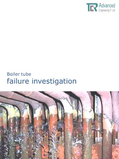
Download the reference documents for this page. Every file is hosted on this domain and is also listed in the site document library.
Related insights
11 published insights on this site bear directly on Boiler Tube Failure Analysis. The 6 most recent are below; the full index carries all 92 Asset Integrity insights.
-
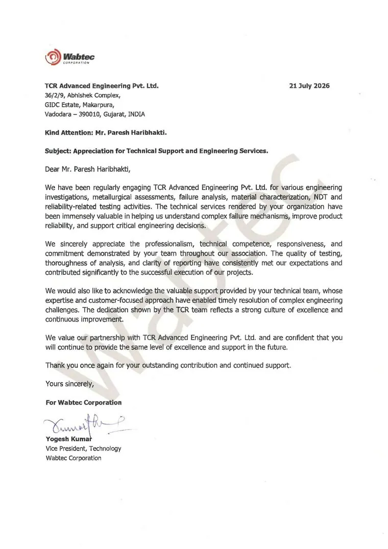
Wabtec Corporation Writes to TCR Advanced: Failure Analysis, Material Characterisation and Reliability Testing
Wabtec Corporation has written to TCR Advanced Engineering to record its appreciation for engineering investigations, metallurgical assessments,…
-
Boiler Tube Failure Analysis
Boiler tube failure analysis reveals the metallurgical evidence behind costly power plant outages and provides proven solutions to prevent recurrence.
-
Boiler Tube Failure Analysis: A Complete Investigation Guide for Power Plants
A complete guide to boiler tube failure investigation: the waterside, fireside, temperature and mechanical damage mechanisms, and how each is proved.
-
Why Failure Analysis Metallurgical Laboratory India Services Prevent Million-Dollar Disasters
Failure analysis metallurgical laboratory India prevents million-dollar disasters. TCR Engineering's 50+ years expertise identifies root causes.
-
Hindalco Commends TCR for Failure Analysis Expertise
TCR Advanced delivers expert metallurgical analysis for Hindalco cranes, ensuring safety, efficiency, and reliability in critical operation
-
Boiler Tube Failure - Book Launch Event
Mr. Paresh Haribhakti has co-authored a book on “Boiler Tube Failures” and this book is published by ASM.

Frequently asked questions
How many boiler tube failure mechanisms are there?
Twenty-two named mechanisms are in general use across the standard taxonomy, grouped as stress rupture, water-side corrosion, fire-side corrosion, erosion, fatigue, and lack-of-quality or maintenance damage. TCR reports against that taxonomy, from a base of 1,500+ documented tube failure investigations.
How do you estimate the tube metal temperature after the failure?
From the tube. Steam-side oxide scale thickness measured metallographically gives an estimate of the accumulated temperature history, and the microstructural degradation stage, spheroidisation through carbide coarsening to creep cavitation, gives an independent read of how far through creep life the material has run. The two are reported together.
How long a tube section should be sent?
At least 300 mm either side of the failure where the outage allows it, so undamaged parent material from the same tube is available as a control. Mark the fireside, the crown and the flow direction before cutting, cut cold where possible, and do not clean the internal surface.
Can the internal deposit be analysed as well as the metal?
Yes, and in a caustic gouging, acid phosphate corrosion or hydrogen damage case the deposit is the primary evidence. It is analysed by EDS and by wet chemical methods. Flushing or wire-brushing the tube before it is sent removes the answer.
Does a tube failure investigation lead to a remaining life assessment?
It does where the evidence points beyond the one tube. The same metallurgical evidence feeds a remaining life assessment of the circuit, and TCR has completed 400+ boiler remaining-life assessments and holds recognition as a Well-Known Remaining Life Assessment Organisation from the Central Boilers Board.
Is TCR recognised under the Indian Boiler Regulations?
Yes. TCR Engineering has been an IBR Well-Known Material Testing Laboratory since 2014, Form XVI-H certificate 38, valid to 2 April 2029.