
Services · Materials Testing
CTOD Testing per BS 7448, ISO 12135 and ASTM E1820
A weld can pass radiography, tensile and Charpy tests and still fracture from a flaw it was allowed to keep. CTOD is the toughness number an Engineering Critical Assessment uses to decide which flaws are safe.
Request a Quote
Overview
TCR Engineering runs crack tip opening displacement (CTOD) testing on welds and parent plate at its Mahape laboratory in Navi Mumbai, India, to BS 7448, ISO 15653, ISO 12135, BS 8571 and ASTM E1820, all on NABL certificate NABLT0726MH18640, from room temperature down to -65 °C and after H2S pre-charging, on specimens 7.5 mm to 90 mm thick.
What does CTOD measure, and why is a CTOD test required?
CTOD is how far the faces of a sharp crack open at its tip before the crack starts to grow. It measures toughness in the presence of a flaw, which a Charpy energy cannot. Specifications call for it wherever a weld must carry a flaw it is allowed to keep: thick sections, low temperatures and high stresses.
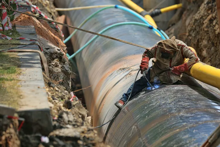
- Pipelines: API 1104 Annex A, where CTOD on weld metal and heat-affected zone sets the flaw acceptance criteria of an Engineering Critical Assessment, which TCR Advanced Engineering delivers and signs on CTOD results from TCR Engineering's Mahape laboratory.
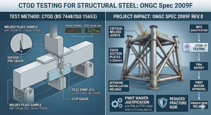
- Offshore structures: ONGC Specification 2009F Rev. 8, where CTOD with a fracture mechanics assessment can support welding without post-weld heat treatment, with the Company's written approval.
- Operator and consultant specifications: ONGC, EIL, DNV and API specifications call for CTOD on welded coupons.
- Pipe mills: seamless and welded line pipe qualified against a project specification, often with a third-party witness.
- Defence: high strength steel weld coupons for naval programmes.
Standards and NABL Scope
Every CTOD method TCR's materials testing laboratory runs is on its NABL ISO/IEC 17025:2017 scope, certificate NABLT0726MH18640, so the report carries the accreditation for the method the specification names. Where a specification names an older edition, such as the 1991 edition of BS 7448, the report states the edition tested to.
| Standard | What it covers | NABL scope |
|---|---|---|
| BS 7448 Parts 1 to 4 | KIc, critical CTOD and critical J: metallic materials (Part 1), welds (Part 2), high loading rates (Part 3) and resistance curves (Part 4) | On the scope, all four parts |
| ISO 15653 | Fracture toughness of welds: notch placement in weld metal and heat-affected zone, and the checks that prove it | On the scope |
| ISO 12135 | The unified method for quasistatic fracture toughness of metallic materials | On the scope |
| BS 8571 | CTOD and J on single edge notched tension (SENT) specimens | On the scope |
| ASTM E1820 | Fracture toughness measurement: J, CTOD and KIc on SENB and C(T) specimens | On the scope |
| ASTM E1290 | The former ASTM CTOD method, now carried in ASTM E1820 and still named by older specifications | On the scope |
Specimens, Notch Location and the Fatigue Pre-crack
A CTOD value is only as good as the place its crack tip sits. The specimen and its report have to show that the notch landed in the zone the specification names, weld metal or heat-affected zone, and that the fatigue pre-crack passes the straightness and validity checks of the standard.
- Geometry: single edge notched bend (SENB) specimens, usually B x 2B, or compact tension C(T) specimens, machined in TCR's own machine shop, 7.5 mm to 90 mm thick, with square-section B x B specimens from 75 mm to 90 mm.
- Notch position: weld centreline, fusion line or a set distance into the heat-affected zone, as the specification requires; for a weld metal test, at least 75 per cent of the crack front must lie in the weld metal.
- Crack front validity: the pre-crack front is measured through the thickness, at nine points under ISO 15653 and ISO 12135, or at 25, 50 and 75 per cent of thickness with crack-to-notch angles where the order asks for it.
- Notch location evidence: post-test metallography shows where the crack tip actually sat; on a heat-affected zone notch, that section is what makes the result valid.
Setting Up a Weld Metal CTOD Programme
A weld metal CTOD programme is fixed by the standard, the weld condition, the test temperature, the acceptance value and the number of specimens. A representative set-up: ISO 15653 weld metal CTOD on a 65 mm butt weld in the as-welded condition, tested at -10 °C against a 0.25 mm minimum, one set of three specimens.
| Item | Set-up |
|---|---|
| Standard and notch | ISO 15653, notch in the weld metal |
| Weld condition | As welded, no post-weld heat treatment |
| Temperature | Fatigue pre-crack grown at room temperature; test at -10 °C |
| Acceptance | Minimum CTOD 0.25 mm |
| Specimens | One set of three |
| Report | CTOD value, load versus COD record and the initial crack length a0; optical metallography of the notch position where required |
| Witness | Client witnesses can attend the test |
As-welded thick coupons carry residual stresses that can bow the fatigue pre-crack front and take a specimen outside the straightness limits. The laboratory can apply the residual-stress modification and precracking techniques of ISO 15653 Annex C, processes C.2, C.3 and C.4, of which C.3 is reverse bending. State in the enquiry which process, if any, the specification requires, so it is agreed before the plate is cut.
Sizing the Test Plate
Each B x 2B SENB specimen for a 65 mm weld comes from a blank 140 mm wide, the full plate thickness and 700 mm long, cut across the weld with the seam at its centre. One set of three needs three such blanks, and machining takes 2 to 4 mm off the thickness.
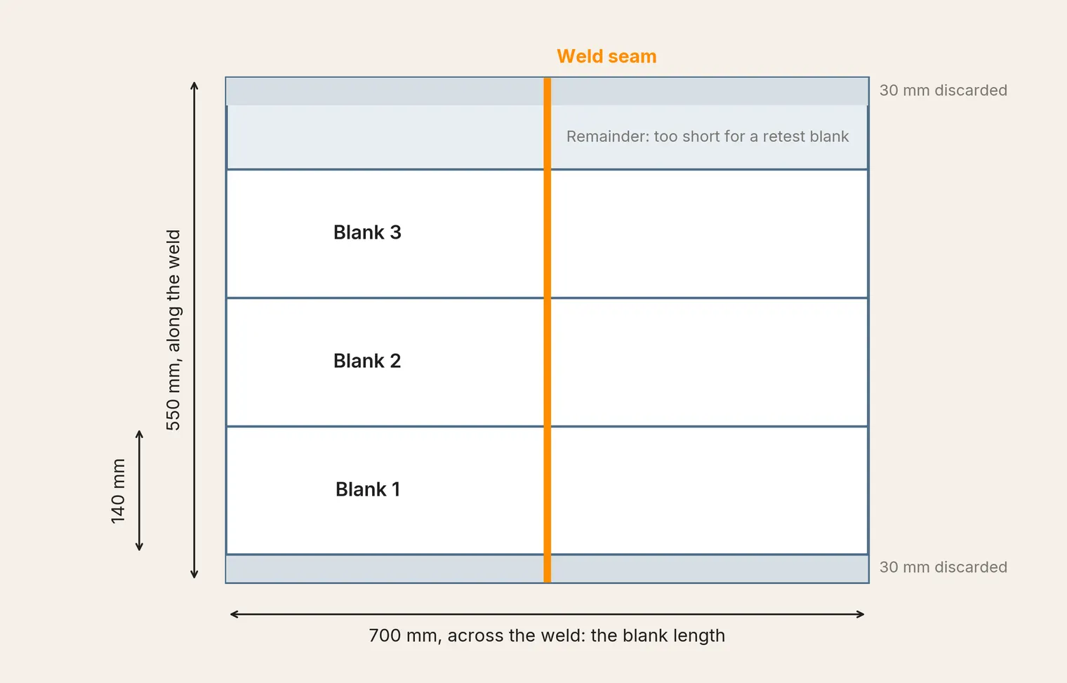
- One plate, one set: a 700 mm x 550 mm plate with the seam across it gives exactly three 140 mm blanks once 30 mm is discarded from each edge, and nothing for a retest.
- Send for retests at the start: supply enough plate for a retest set with the first consignment, so a retest does not wait for new welding.
- B x B specimens: about 75 mm wide x full thickness x 350 mm per blank, but ISO 12135 recommends B x B only for material 75 mm and thicker; on a 65 mm weld it is an exception the client must accept.
Test Temperatures
The test temperature comes from the minimum design temperature of the structure, and a CTOD result belongs to that temperature only. TCR runs CTOD at room temperature, at sub-zero temperatures down to -65 °C in either of its two cold chambers, and at -45 °C for welding electrodes.
| Temperature | Typical programme |
|---|---|
| Room temperature | ASTM E1820 CTOD on C(T) specimens; thick weld coupons, 30 mm to 70 mm |
| 0 °C | ONGC Specification 2009F Rev. 8, where the welding procedure must reach at least 0.20 mm; seamless tube qualification against a 0.2 mm minimum on base metal |
| -10 °C | ISO 15653 and ISO 12135 weld CTOD on C(T) specimens 40 mm and 60 mm thick, for the weldability qualification of a newly developed steel |
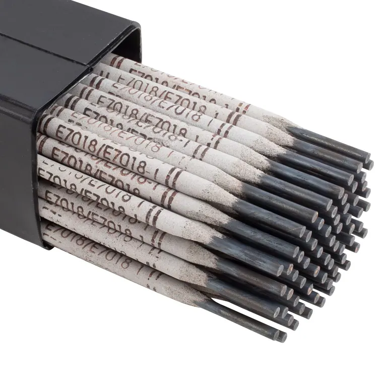
| -45 °C | Welding electrodes E7018 and E7018-1, on plates welded to the procedure being qualified |
| Down to -65 °C | Sub-zero CTOD in either cold chamber, including Arctic and offshore material qualification |
CTOD After H2S Hydrogen Pre-charging
In wet hydrogen sulphide service, hydrogen diffuses into the weld and lowers its toughness. TCR's procedure, developed for Larsen and Toubro, charges the pre-cracked specimen in H2S before the CTOD test, so the result is the toughness the weld keeps in service rather than in clean air.
- Charging basis: at least 96 hours in NACE TM0177 Solution A saturated with H2S, with loading inside the window the procedure allows after removal.
- Standards: CTOD per ISO 15653, ISO 12135 or BS 8571, with the fracture face examined for hydrogen damage and reported with the CTOD value.
- Comparison: where the specification asks for both, CTOD in air and after charging on the same weld show how much toughness hydrogen takes away.
The H2S bench is the one that runs HIC and SSC qualification on the corrosion and sour service page; hydrogen embrittlement that does not come from H2S, such as cylinder steel and plated parts, is on the hydrogen embrittlement page.
CTOD Programmes Delivered
TCR Engineering has delivered CTOD programmes for an Indian steelmaker, three Indian pipe mills, a UAE marine engineering contractor and DRDO's Naval Materials Research Laboratory. The orders show what buyers check beyond the CTOD value: that the notch sits where intended, that the fatigue pre-crack front is measured through the thickness, and that the test is witnessed and reported under NABL.
| Client and year | Scope and standard |
|---|---|
| Welspun Corp Limited, Anjar, Gujarat (Barossa project) 2023 | 24 CTOD tests on SENB specimens with straight notch, up to 25 mm thick, with load versus clip-gauge (COD) records; 6 optical metallography examinations to confirm notch location after fracture Standard: Client project specification |
| Aries Marine & Engineering Services LLC, Sharjah, UAE 2023 | CTOD at room temperature, at maximum load, on a C(T) specimen with straight notch, 8.0 mm thick, machined by TCR Standard: ASTM E1820 |
| Jindal SAW Limited, Seamless Tubes Division, Nashik 2024 | Two sets of three specimens, one longitudinal and one transverse, at 0 °C against a 0.2 mm minimum on base metal; fatigue pre-crack front measured at 25, 50 and 75 per cent of thickness with crack-to-notch angles; witnessed by a third-party inspector and reported under NABL Standard: BS 7448 (1991 edition specified) |
| Maharashtra Seamless Limited, Roha 2025 | Six CTOD specimens for seamless line pipe to API 5L (46th edition), with machining and full fatigue pre-crack front data Standard: BS 7448 |
| ArcelorMittal Nippon Steel India (AM/NS India), Hazira, Gujarat (Drydocks World project, Dubai) 2025 | Weldability qualification of a newly developed steel: CTOD on 40 mm and 60 mm thick C(T) specimens with straight notch, machined by TCR with the notch in the weld to EN 10225; fatigue pre-crack grown at room temperature, test at -10 °C; post-test metallography; reported under NABL Standard: ISO 15653 and ISO 12135 |
| Naval Materials Research Laboratory (NMRL), DRDO, Ministry of Defence, Ambernath 2024 to 2027 | CTOD on 29 specimens from high strength steel weld coupons up to 70 mm thick, at room temperature and sub-zero (30 mm to 70 mm at room temperature, 8 mm to 30 mm down to -20 °C); the same contract covers tensile, Charpy, bend, radiography, chemical analysis and metallography of the coupons Standard: ASTM E1820; ASTM E8M, E23, E190, E94 |
For Saudi Aramco's Jafurah gas compression plants (PWIS Package-1, 2024 to 2025), six CTOD tests per pipeline on pre-cracked specimens were the fracture toughness input to the ECA of 42-inch girth welds per API 1104 Annex A Option 2. Defence work runs under long-term contracts from NMRL and DMRL, with approvals from CQAE, DRDO.
What to Send Before Testing
Most CTOD delays start before the sample arrives: a test plate welded at the wrong heat input, or too little parent metal to machine the specimen with its notch on the weld centreline. Agree the standard, the notch positions, the temperature and the specimen count before the plate is welded.
- Test plates welded to the procedure being qualified, with enough parent metal either side for a B x 2B specimen. For electrode qualification, plates of 250 mm x 25 mm x 250 mm with the weld at the centre.
- The specification and its clause: standard and edition, notch positions, test temperature, acceptance value and any witness requirement.
- Specimen count: at least three valid specimens per notch position, and six where CTOD in air and after H2S charging are both required.
- For ONGC work: a test plate whose carbon equivalent is within 0.02 of the maximum production value, welded at the highest production heat input.
- International shipments: the shipping invoice states that the material has no commercial value and is sent for testing only.
What the CTOD Report Records
A CTOD report has to let a fracture mechanics engineer use the number without calling the laboratory. It carries the value and its type, the record it was calculated from, and the evidence that the specimen was valid: crack front shape, notch location and the temperature the specimen was actually at.
- The CTOD value and its type: δc, δu or δm.
- The load versus crack mouth opening (clip gauge) record.
- Specimen dimensions, orientation and notch position.
- Pre-crack front measurements and the validity checks of the standard.
- Post-test metallography photomicrographs, where ordered.
- The standard and edition, the decision rule and the NABL accreditation.
- Conformity to a minimum such as 0.25 mm is stated with a simple acceptance decision rule, measurement uncertainty not considered, unless the client asks for a guard band; a guard band is applied per ILAC G8:09/2019 at 1U.
Related services and industries
- Fatigue and Fracture Toughness Testing
- Engineering Critical Assessment
- Mechanical Testing
- Welder Qualification
- Corrosion and Sour Service Testing
- Hydrogen Embrittlement Testing
- Metallurgical Evaluation
- Machine Shop and Specimen Preparation
- Pipelines and City Gas
- Oil and Gas Upstream
- Marine and Offshore
- Aerospace
Documents
Download the reference documents for this page. Every file is hosted on this domain and is also listed in the site document library.
Related insights
7 published insights on this site bear directly on CTOD Testing. The 6 most recent are below; the full index carries all 167 Materials Testing insights.
-
CTOD Testing for Structural Steel as per ONGC Spec 2009F
TCR Engineering explains CTOD testing requirements for structural steel under ONGC Spec 2009F Rev.8, including FMA, specimen prep, and accreditation.
-
CTOD Testing with H2S Hydrogen Pre-Charging: What Sour Service Projects Actually Require
TCR Engineering runs CTOD fracture toughness testing with H2S hydrogen pre-charging to ISO 15653, ISO 12135, and NACE TM0177, for sour service weld…
-
CTOD Testing for Welding Electrodes: The Complete Guide to Fracture Toughness at -45°C
TCR Engineering's comprehensive CTOD testing ensures welding electrode performance at extreme temperatures following ISO 15653 standards.
-
ONGC Specification Testing: Your Complete Guide to Mechanical, Corrosion, and CTOD Testing
TCR Engineering conducts comprehensive ONGC specification testing including mechanical properties, corrosion resistance, and CTOD evaluation.
-
CTOD Fracture Toughness Testing Laboratory - Why Your Pipeline's Survival Depends on Getting This Right
CTOD fracture toughness testing laboratory: TCR Engineering runs BS 7448 and ASTM E1820 tests from +24°C to -65°C in Navi Mumbai, under NABL accreditation.
-
CTOD Fracture Toughness per ASTM E1820 in India
TCR Engineering runs ASTM E1820 CTOD testing from room temperature down to -65°C in two cold chambers, on specimens 7.5 mm to 90 mm thick.


Frequently asked questions
What is a CTOD test?
Crack tip opening displacement is a fracture toughness test. A specimen with a sharp fatigue pre-crack is loaded at the specified temperature, and the opening at the crack tip is measured where the crack starts to grow unstably or the load peaks. The value, in millimetres, feeds a fitness-for-purpose assessment of flaws.
Which CTOD standards are on TCR's NABL scope?
BS 7448 Parts 1 to 4, ISO 15653, ISO 12135, BS 8571, ASTM E1820 and ASTM E1290 are all on NABL certificate NABLT0726MH18640 at the Navi Mumbai laboratory, so a CTOD report to any of them carries the accreditation.
How cold can TCR run a CTOD test?
Room temperature and sub-zero tests down to -65 °C run in either of TCR's two cold chambers, welding electrodes are qualified at -45 °C, and Arctic and offshore qualification runs inside the same range. The temperature comes from the specification, not from the laboratory.
Can TCR test CTOD after H2S pre-charging?
Yes. Specimens are charged for at least 96 hours in NACE TM0177 Solution A saturated with H2S and loaded within 20 minutes of removal, per ISO 15653, ISO 12135 or BS 8571. The procedure was developed for Larsen and Toubro.
How many CTOD specimens are needed?
At least three valid specimens per notch position for most specifications, and six where results in air and after H2S charging are both required. The ECA coupons of an API 1104 Annex A assessment carry six CTOD tests per pipeline, across weld metal and heat-affected zone.
Do as-welded thick coupons need special preparation before CTOD?
They can. As-welded thick coupons carry residual stresses that can bow the fatigue pre-crack front. TCR can apply the residual-stress modification and precracking techniques of ISO 15653 Annex C, processes C.2, C.3 and C.4. State in the enquiry which process, if any, the specification requires, so it is agreed before the plate is cut.
Why is a CTOD test required for welded joints?
Because a weld may carry flaws that fabrication inspection allows, and a Charpy energy cannot say whether a flaw of a given size will fracture. CTOD measures toughness at a sharp crack at the design temperature, and an Engineering Critical Assessment uses that value to set the flaw sizes a pipeline or offshore weld may keep without repair.