
Services · Non-Destructive Testing
Tank Floor MFL Scanning per API 653
A floor that looks sound from inside the tank can be losing metal from underneath. Magnetic flux leakage reads both faces of every plate in one pass, and tells you which face is corroding.
Request a QuoteOverview
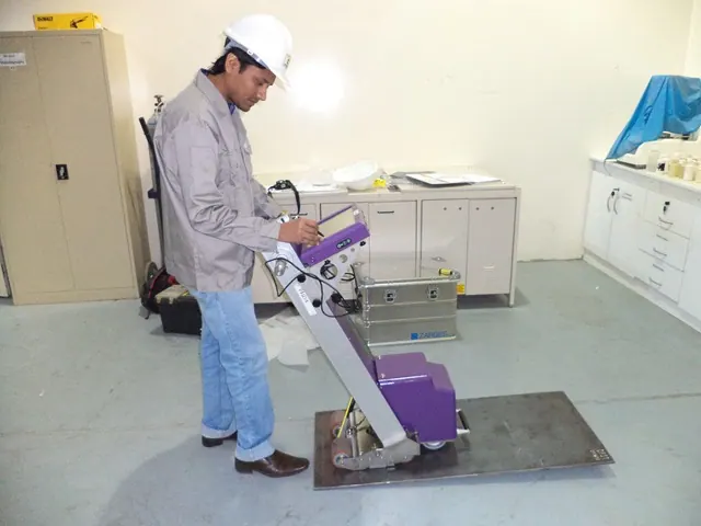
TCR scans above-ground storage tank floors by magnetic flux leakage (MFL) during an out-of-service inspection, mapping product-side and soil-side corrosion plate by plate, proving up indications by ultrasonic thickness measurement and covering the weld margins by UT. TCR Arabia has run MFL tank floor scanning in Saudi Arabia since 2012; the result feeds the API 653 inspection.
What MFL Finds on a Tank Floor
A tank floor corrodes from two faces: the product side, where water and sludge settle, and the soil side, where the foundation, drainage and cathodic protection decide the rate. Spot ultrasonic readings sample a few points of a floor that may cover thousands of square metres. MFL scans the whole plate area and finds the loss wherever it sits.
- What it detects: pitting, general metal loss and erosion in carbon-steel floor and annular plates.
- Which face: the scanner discriminates product-side from soil-side loss, so a floor losing metal underneath is not mistaken for one that needs a new lining.
- How it works: magnets saturate the plate; where metal is missing, the field leaks out of the steel and the sensors between the poles read the leak.
- What it does not give on its own: a certified remaining thickness. Every significant indication is proved up by ultrasonic thickness measurement before it is reported as a number.
How a Floor Scan Runs
MFL is an out-of-service method: the tank is emptied, cleaned and made safe for entry, and the scan is only as good as the floor it is run on. Magnetic debris and weld spatter give false indications, so the cleaning standard is agreed before the team mobilises, not argued on the day.
- Plate layout. The floor drawing, or a layout surveyed on entry, gives every plate a number so that each indication is reported against a plate and a position, not a photograph.
- Floor preparation. Sludge, scale, loose coating, magnetic debris and weld spatter removed to the agreed standard.
- Set-up and reference check. The scanner is set for the plate thickness and the coating, and verified on a reference plate before the floor is scanned.
- Scan. Plate by plate in overlapping lanes, the encoder recording position as the scanner travels. The instrument maker states the FloormapVS2i encoder accurate to within 3 mm over an 8-metre track, with annual calibration.
- Mark and prove up. Indications above the reporting threshold are marked on the plate and measured by ultrasonic thickness gauging, which sets the number that is reported.
- Cover what the scanner cannot reach. The margins beside lap welds and the shell-to-annular weld, and a small square at each plate corner, are examined by ultrasonic testing and recorded as such.
- Report. The floor map, the proved-up thicknesses and the register of untested areas, handed to the API 653 inspection of the tank.
What the Scanner Covers, and What It Does Not
Every floor method has limits, and a report that hides them is worse than a smaller scan. The limits below are stated on every TCR MFL report, together with the areas left to ultrasonic testing, so the owner can see exactly which part of the floor the conclusion rests on.
| Aspect | Position |
|---|---|
| Plate thickness | Floor plates from 6 mm to 20 mm, the range TCR Arabia states for its tank floor MFL service. Sensitivity falls as the plate gets thicker |
| Coated floors | Inspected through the coating; the coating thickness that still allows a satisfactory scan falls as the plate gets thicker, and is agreed per tank |
| Annular plates and weld margins | The steerable scanner reaches the annular plates and close to the plate welds; the strip it cannot reach is examined by UT |
| Plate corners | A small square at each corner of a floor plate cannot be scanned and is examined by UT |
| Surface condition | Magnetic debris and weld spatter produce false indications; cleaning is part of the scope |
| Tank status | Out of service, cleaned and gas-free. For a tank that must stay in service, see the methods below |
What the Report Contains
The MFL report is written for the person who has to decide which plates to repair, patch or replace, and for the inspector who signs the API 653 bottom evaluation. It separates what was measured from what was screened, and names every area that was not examined by either method.
- A floor map, plate by plate, with every indication located and classified as product-side or soil-side.
- The ultrasonic prove-up value against each significant indication, with the instrument identified.
- The minimum remaining thickness found on each plate and on the annular ring.
- A register of untested areas: weld margins, plate corners and any plate the scan could not cover, with the method used there instead.
- The data the API 653 bottom evaluation needs: remaining thickness, the side the loss is on, and its distribution across the floor.
- Where the floor is borderline, the inputs for a fitness-for-service assessment rather than a replacement recommendation made on the scan alone.
Where MFL Sits Among the Tank Methods
MFL is the method for the whole floor when the tank is open. It is one of several tests an API 653 inspection draws on, and each answers a different question. The full inspection, with every test and how the results are put together, is described on storage tank inspection and audit per API 653.
| Method | Tank status | What it answers |
|---|---|---|
| Magnetic flux leakage floor scanning (this page) | Out of service | Where the floor is losing metal, on which face, across the whole floor |
| Acoustic emission testing | In service | Whether the floor is actively corroding or leaking now, graded I to IV, and when to open the tank |
| Robotic in-service tank inspection | In service | Ultrasonic thickness of the floor without draining or entry |
| Advanced ultrasonics | Either | Shell corrosion mapping and weld examination by PAUT |
| Conventional NDT | Out of service | Vacuum box testing of floor welds, MT and PT of shell-to-floor and nozzle welds, UT thickness of the shell courses |
Who Delivers It
TCR Arabia, the group's 60/40 joint venture in Dammam, acquired the Silverwing FloormapVS2i computerised floor scanner in 2012 and has run MFL tank floor scanning in Saudi Arabia since, with tank floor jobs at petrochemical sites in Jubail recorded in its 2025 project register. Across India and the GCC, MFL is the method TCR uses most for tank bottom plates.
- Instrument: Silverwing FloormapVS2i, a computerised MFL tank bottom scanner with automatic feature sizing and product-side and soil-side discrimination.
- Prove-up: ultrasonic thickness gauging, and phased array ultrasonics where an indication needs to be characterised.
- Inside Saudi Arabia: delivered by TCR Arabia Company Limited.
- Elsewhere: scoped per enquiry, with the instrument, the team and the reporting standard agreed before mobilisation.
Related insights
2 published insights on this site bear directly on Tank Floor MFL Scanning. They are below; the full index carries all 80 Non-Destructive Testing insights.
-
TCR's Inspection Strategies for Aboveground Storage Tanks
Tank integrity with advanced NDT solutions like AE, MFL, PAUT & robotic inspections, ensuring safety, compliance, and longevity
-
TCR Arabia now undertakes MFL Testing
Detect and size underfloor corrosion for above ground storage tanks

Read all 80 Non-Destructive Testing insights →All insights →
Frequently asked questions
Does the tank have to be emptied for MFL floor scanning?
Yes. MFL is run from inside the tank, so the tank is taken out of service, emptied, cleaned and made safe for entry. For a tank that must stay in service, acoustic emission testing screens the floor for active corrosion and leaks, and robotic in-service inspection measures floor thickness without draining.
Can MFL tell product-side corrosion from soil-side corrosion?
Yes. The FloormapVS2i discriminates between loss on the top face and loss on the underside of each plate, so the report separates internal corrosion from soil-side corrosion instead of giving one combined figure.
What floor thickness can be scanned?
TCR Arabia states its tank floor MFL service for plates from 6 mm to 20 mm. Sensitivity falls as the plate gets thicker, and the coating thickness that still allows a satisfactory scan falls with it, so both are confirmed per tank before the team mobilises.
What happens to the areas the scanner cannot reach?
The strip beside lap welds and the shell-to-annular weld, and a small square at each plate corner, are examined by ultrasonic testing. The report lists every such area and the method used there, so no part of the floor is reported as scanned when it was not.
Does MFL give the remaining plate thickness?
MFL locates and sizes metal loss across the floor. Every significant indication is then proved up by ultrasonic thickness measurement, and the reported remaining thickness is the ultrasonic value, with the instrument identified.
How does an MFL scan fit into an API 653 inspection?
It supplies the floor data for the bottom evaluation: remaining thickness, which face the loss is on and how it is distributed. The shell, roof, welds, foundation and appurtenances are covered by the other tests in the API 653 inspection, described on the storage tank inspection and audit page.