
Services · Non-Destructive Testing
Acoustic Emission Testing (AET) per ISO 24489 and ASME Section V
A tank floor cannot be seen while the tank is full. It can be heard. An hour of listening tells you which part of the floor needs the next inspection, and which part can wait.
Request a QuoteOverview
TCR provides acoustic emission testing (AET) of in-service storage tank floors and of metal and FRP pressure vessels under load, on a Vallen AMSY-6 system, with the field team mobilising from Vadodara to sites in India and overseas. ASNT Level II technicians certified in acoustic emission run each examination and grade the result to ISO 24489, ASTM E1930 or ASME Section V.
What Acoustic Emission Testing Tells You
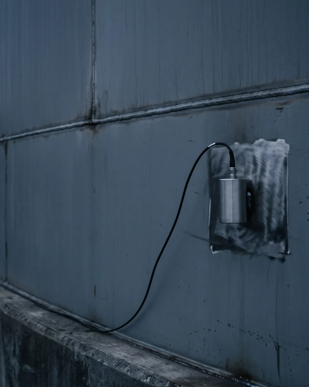
Acoustic emission testing listens for the stress waves a structure releases while it is damaging itself: a corrosion product fracturing, a crack extending, a leak jetting through the floor. Piezoelectric sensors on the outside of the shell pick those waves up, and the arrival times across the sensor array place the source. It finds activity, not geometry.
- What it reports: where on the structure damage is active during the monitoring window, and how intense that activity is.
- What it needs: a stimulus. A settled liquid load for a tank floor, a controlled pressure rise for a vessel. A structure under no change of load is largely silent.
- What it does not report: remaining wall thickness, flaw size or pit depth. Those come from the follow-up NDT the AE result directs.
- Why operators use it: it covers the whole floor or shell from outside, without draining, cleaning or entering the tank, so the out-of-service inspection budget goes to the tanks and zones that are actually active.
Where TCR Applies Acoustic Emission
Acoustic emission is one method applied to several assets, and the governing document changes with the asset and the stimulus. The examination plan is written to the standard the enquiry names, and agreed before the team mobilises. Above-ground storage tank floors are the application behind the worked example further down this page.
| Asset | Stimulus | Governing documents | What the report gives |
|---|---|---|---|
| Above-ground storage tank floors, in service | Product held at 50% or more of safe fill height, settled 12 to 24 hours | ISO 24489:2024; ASTM E1930/E1930M-25; EN 15856 | Active-corrosion and leak zones on the floor, a grade, and a re-inspection interval |
| Tank shells and roofs, new or in service | Controlled filling with hold periods | ASTM E1930/E1930M-25 | Active sources in the stressed shell areas |
| Metal pressure vessels, columns and bullets | Hydrostatic or pneumatic pressure test, or a controlled pressure rise | ASME BPVC Section V, Article 12; EN 14584; ASTM E569 | Located active sources, for follow-up NDT |
| FRP and GRP tanks and vessels, new or in service | Pressurisation or filling in load steps with holds | ASTM E1067/E1067M-25; ASME BPVC Section V, Article 11 | Evaluation against the practice's criteria for each load step |
How a Tank Floor Examination Runs
The floor cannot be reached while the tank is in service, so the sensors go on the lower shell and the product itself becomes the load. Most of the work is in getting the tank quiet enough to hear: a floor examination fails on noise far more often than on sensitivity.
- Method statement. Written from the tank drawings: diameter, internal arrangement, the location of any repairs and patch plates, and how any cathodic protection anodes connect to the bottom plate.
- Fill and settle. The tank is filled to at least 50% of its safe fill height, preferably 90%, isolated, and left to settle: 24 hours for heavy products such as crude oil, 12 hours for lighter products.
- Silence the tank. Inflow and outflow stopped, penetrations sealed, pumps, agitators, heaters and bubbler or ultrasonic level gauges switched off, and vehicle movement and work on adjacent tanks held for the test window.
- Noise survey. Background levels read at ground-level nozzles, valves, manholes and points along the stairway before any data is recorded.
- Mount the sensors. Resonant low-frequency sensors on bare metal, coating removed at each position and a 20 × 20 cm window cut where the tank is insulated, held by magnetic holders over couplant and spaced equally around the circumference. A large tank takes two rings, one 0.3 to 0.5 m and one 1 to 2 m above the bottom plate.
- Verify the array. Every sensor is checked with a pencil-lead break before monitoring starts and again when it ends, so a sensor that lost coupling during the test is found rather than read as a quiet zone.
- Monitor. A minimum of one hour of data with the test conditions held. Rain, lightning and high wind stop the test.
- Analyse and grade. Noise is filtered out, the remaining events are located zone by zone, leak-type activity is separated from corrosion-type activity, and the floor is graded.
How the Floor Is Graded
The grade answers the question a tank owner actually has: when does this floor next need attention. TCR reports on a four-grade scale, and the grade carries the recommended interval to the next examination. The final interpretation is settled with the owner, because the same grade means different things on a crude tank and on a fire water tank.
| Grade | Floor condition | Recommendation |
|---|---|---|
| I | No active sources | Monitor again after 4 years |
| II | Low active corrosion | Monitor again after 2 years |
| III | Medium active corrosion | Monitor again after 1 year |
| IV | Leaks or high active corrosion | Follow-up inspection at the first available opportunity |
A grade can be global or local. Where activity clusters in one zone, the report grades that zone and says how the rest of the floor behaved, so a follow-up inspection is aimed at a sector of the floor, not the whole tank.
A Worked Example: Five Sensors, One Hour Twenty-Five Minutes
The figures below come from TCR's acoustic emission demonstration report, the document that shows a buyer exactly what a TCR AET report contains. The tank is a vertical above-ground storage tank of 8,040 mm diameter; the plant and the owner are not named.
| Parameter | As examined |
|---|---|
| Sensor count | Five. Each sensor covers about 8 m of shell, so a circumference of about 25 m needs four at minimum; five were used |
| Sensor layout | 72° apart, about 5.02 m of arc between sensors, 1.26 to 1.55 m above the floor, numbered from the pump house side |
| Load condition | Liquid above 68% of capacity, held for more than 12 hours before the test |
| Sensors and filter | VS30-SIC 46 dB resonant sensors, 25 to 80 kHz; 25 to 45 kHz band filter |
| System check | Pencil-lead break at every sensor, average response 88 dB |
| Noise and threshold | Background 42 dB; evaluation threshold 12 dB above it |
| Location | Zonal, at least three sensors to locate an event, maximum delta-T 3.07 ms, wave velocity 3,250 mm/ms |
| Monitoring | 1 hour 25 minutes recorded; 1 hour analysed in VisualAE |
The analysis found 217 valid events across the floor, and 130 of them located in one zone, near sensor 1 on the pump-house side. The zones near sensors 2 to 5 showed low activity. No active leak was indicated.
- Grade: IV, localised to the zone near sensor 1; the rest of the floor low.
- Evidence in the report: channel against hits, amplitude against hits, counts against amplitude, a transient waveform from sensor 1, cumulative energy against counts, and a severity map of the floor.
- Recommendation: follow-up NDT in the active zone at the first available opportunity: visual inspection, ultrasonic thickness measurement, liquid penetrant testing of the weld joints and vacuum box testing.
That is the value of the method in one line: a whole floor screened in an hour and a half, and the out-of-service inspection pointed at one sector of it.
The Instrument
TCR's acoustic emission system is a Vallen AMSY-6, built by Vallen Systeme in Germany, in an MB19-V2 main chassis. The platform is modular: each ASIP-2 signal processor board carries two channels, an MB19 chassis takes up to 38 channels, and the AMSY-6 architecture extends to 254 parallel channels across chassis.
- Signal processing: ASIP-2/S dual-channel processors; the ADC samples at 40 MHz with 16-bit resolution.
- Sensors: Vallen VS30-SIC 46 dB resonant sensors for tank floor work, on MAG4SI magnetic holders.
- Software: VisualAE for location, filtering and the severity map; transient waveforms are recorded for the events that matter.
- Verification: a pencil-lead break at every sensor before and after each test, with the gain, noise and threshold of every channel recorded in the report.
Who Runs the Examination
Acoustic emission is interpreted, not just recorded, so the people matter as much as the instrument. TCR's AE team is two Level II technicians, each certified in acoustic emission after a general, specific and practical examination. The field team is drawn from TCR Advanced Engineering in Vadodara, which also issues the AET report.
| Person | Certification | Method scope | Valid to |
|---|---|---|---|
| Nikhil Sabhaya | Level II, acoustic emission testing, certificate TCRADV/026/121 | Acoustic emission; also holds a five-method ASNT NDT Level III (ET, UT, PT, MT, VT) | 28 February 2031 |
| Harsh Gandhrokiya | Level II, acoustic emission testing, certificate TCRADV/026/120 | Acoustic emission | 28 February 2031 |
Both Level II certificates were issued on 10 February 2026 under written practice TCR/NDT/SNT-TC-1A Rev. 8, which follows ASNT Recommended Practice SNT-TC-1A, 2024 edition. A standard field deployment is one team of two: a Level II technician and an assistant. The broader Level III bench is offered as its own service, ASNT Level III consultancy.
What the Site Has to Provide
An AE examination is only as good as the quiet the site can give it. The list below is agreed in writing before the team travels, because a tank that is not filled, settled and isolated when the team arrives cannot be tested that day.
- Tank drawings, internal arrangement, repair history with patch plate locations, and cathodic protection anode connection details, before the method statement is written.
- Material grade, diameter, shell thickness and the standard to be followed.
- The tank filled and settled as above, isolated, with penetrations sealed and pumps, agitators, heaters and mixers stopped.
- Coating removal at each sensor position, and insulation windows where the tank is insulated, with reinstatement afterwards.
- Scaffolding or access where sensor positions need it.
- A stable single-phase supply through an online UPS within about 10 m of the shell.
- Gate passes, work permits and a safe place in the plant to keep the equipment.
- A test window free of rain, lightning, high wind, vehicle movement near the tank and activity on adjacent tanks.
What the Report Contains
A TCR AET report is written so that the reader who did not attend can check every step: how the tank was loaded, where each sensor sat, how the system was verified, what was recorded and why the grade follows from it. A preliminary report is issued once all required data is in hand, and the final report follows the team's return to the laboratory.
- Equipment and tank details, and the instrument by make, model and serial number.
- The procedure and the standards it is written to.
- The sensor layout as a table and a drawing: position, height above the floor and spacing around the circumference.
- Test parameters: location type, sensor count, noise level, evaluation threshold, filters, wave velocity and temperature during the test.
- Gain, noise and threshold for every channel at calibration.
- Site photographs of the system and of each sensor mounting.
- Results as graphs and a severity map of the floor.
- A summary, the grade, and the recommended follow-up with named methods.
What Acoustic Emission Cannot Do, and What Follows It
AE is a screening method, and its value depends on what is done with the answer. An active zone is a question for the next inspection, not a measurement of wall loss. A dormant defect makes no noise, so a Grade I floor is one that was not actively corroding during the test, not one with no metal loss.
- Sizing and thickness: by magnetic flux leakage floor scanning and ultrasonic thickness mapping during an out-of-service storage tank inspection per API 653.
- Without taking the tank out of service: robotic in-service tank inspection puts ultrasonic measurement on the floor itself.
- Weld joints and leak paths: liquid penetrant and vacuum box testing under conventional NDT.
- Deciding whether the floor can run to the next turnaround: fitness-for-service assessment on the measured wall loss.
- Temperature and noise limits: the standard set-up assumes an ambient-temperature shell and a quiet tank; a hot or noisy asset is assessed at the enquiry stage, before a test is offered.
Related services and industries
Related insights
2 published insights on this site bear directly on Acoustic Emission Testing. They are below; the full index carries all 80 Non-Destructive Testing insights.
-
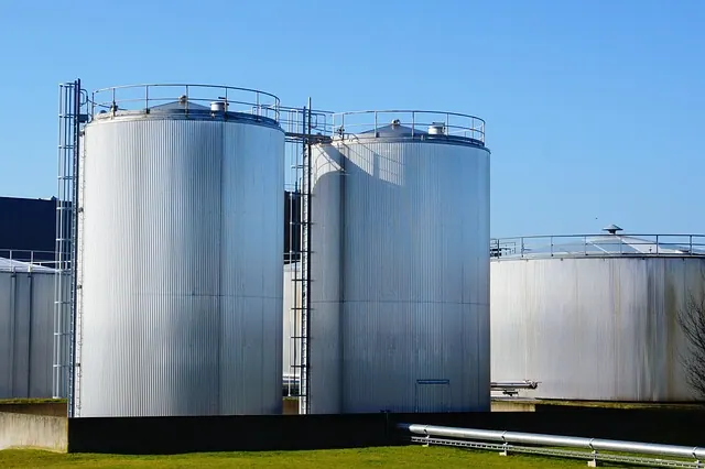
Advanced Acoustic Emission Testing Services: TCR Engineering's Expertise in Critical Asset Inspection
TCR Engineering offers advanced Acoustic Emission Testing services using Vallen AMSY-6 technology for storage tanks & pressure vessels
-
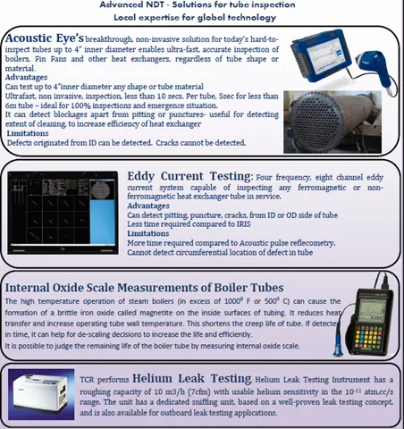
TCR’s Advanced NDT Solutions for Tube Inspection
Undertaking Acoustic Eye, Eddy Current, Oxide Scale Measurement and Helium Leak Test
Read all 80 Non-Destructive Testing insights →All insights →
Frequently asked questions
What does acoustic emission testing detect on a storage tank floor?
It detects active corrosion and active leaks on the floor while the tank is in service. Sensors on the lower shell pick up the stress waves those processes release, locate them zone by zone, and the floor is graded I to IV with a recommended interval to the next examination. It does not measure remaining thickness.
Does the tank have to be emptied for an AET examination?
No. That is the point of the method. The tank stays in service, filled to at least 50% of its safe fill height and preferably 90%, isolated, and settled for 24 hours for heavy products such as crude oil or 12 hours for lighter products before monitoring starts.
How long does an acoustic emission test take?
Monitoring runs for a minimum of one hour with the test conditions held. With the tank filled, settled and isolated before the team arrives, one tank a day is the working estimate. A preliminary report and then the final report follow, with their dates confirmed in the quotation.
Who performs acoustic emission testing at TCR?
Two Level II technicians, Nikhil Sabhaya and Harsh Gandhrokiya, each certified in acoustic emission under written practice TCR/NDT/SNT-TC-1A. The field team is drawn from TCR Advanced Engineering in Vadodara.
Can AET be used on FRP vessels during a hydrostatic test?
Yes. ASTM E1067/E1067M-25 and ASME BPVC Section V, Article 11 cover acoustic emission examination of fibre reinforced plastic tanks and vessels, new or in service. The vessel is loaded in steps with holds and evaluated at each step. The load schedule and the acceptance criteria are agreed from the enquiry before mobilisation.
Is acoustic emission testing NABL accredited?
No. Acoustic emission is not a NABL accredited test at TCR. AET reports are issued by TCR Advanced Engineering, Vadodara, which holds NABL ISO/IEC 17025:2017 certificate TC-6739, valid to 13 October 2029, and each report names the procedure and the standard the examination was run to.