
Services · Materials Testing
Hydrogen Induced Disbonding Testing per ASTM G146
A weld overlay can pass every fabrication check and still lift off the shell after the first shutdown. ASTM G146 finds that out in an autoclave, before the reactor does.
Request a Quote
Overview
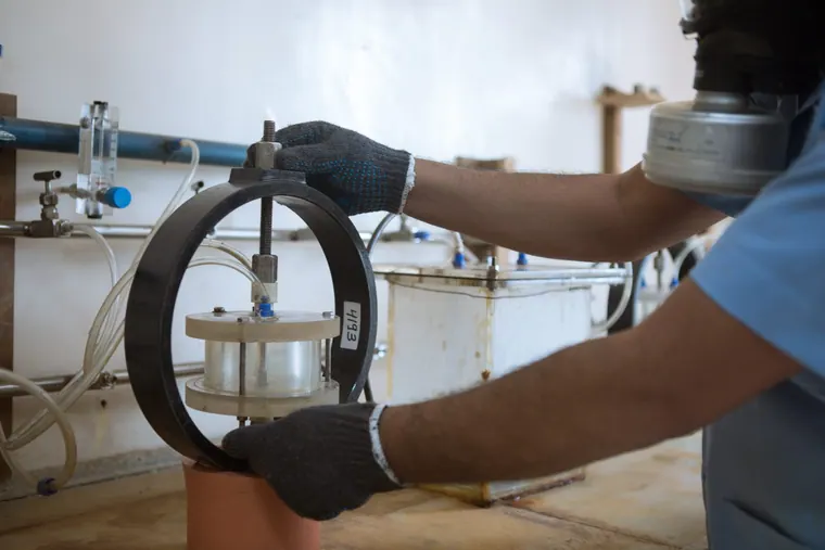
TCR Engineering runs hydrogen induced disbonding (HID) testing per ASTM G146 at its Mahape laboratory in Navi Mumbai, on stainless alloy weld overlay and clad steel intended for high-pressure, high-temperature refinery hydrogen service. The laboratory is NABL accredited under certificate NABLT0726MH18640; ASTM G146 is not yet on that scope and is reported outside it.
What ASTM G146 Evaluates
ASTM G146 is the standard practice for evaluating disbonding of bimetallic stainless alloy/steel plate for refinery high-pressure, high-temperature gaseous hydrogen service. It indicates whether a metallurgically bonded stainless layer resists hydrogen induced disbonding. The current edition is ASTM G146-24, published in May 2024, superseding G146-01 (reapproved 2018).
- Product forms: weld overlay primarily, and by clause 1.2 also hot roll bonded, explosion bonded and other processes that put a stainless alloy on a steel substrate.
- Service it models: hydroprocessing duty, where the vessel wall is charged with hydrogen at pressure and temperature in operation and then cooled at every shutdown.
- What it ranks: material composition, processing method, fabrication technique and heat treatment, against hydrogen partial pressure, service temperature and cooling rate.
- Where the limit comes from: the purchase specification. Where it sets an acceptance limit on disbonded area, the report is read against that limit.
The Test Specimen and the Calibration Block
The specimen is a cylinder machined from a stainless alloy/steel plate made by the same methods intended for the equipment itself, so the bond under test is the bond that will go into service. A separate calibration block carries the ultrasonic reference that disbonding is read against.
| Feature | Requirement |
|---|---|
| Diameter | 73 ± 2 mm |
| Thickness | 45 ± 2 mm, reduced to the plate thickness where the material is thinner |
| Qualification cladding | 6 ± 1 mm on the top face |
| Side cladding | Overlay welded around the circumference, after the initial dimensions are measured |
| Calibration block | 3 mm diameter flat-bottom hole drilled through the cladding thickness to the cladding/steel interface, scanned from the steel face |
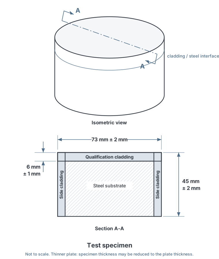
Three measurements are taken before the side overlay is welded and are recorded with the specimen: the specimen diameter, the specimen thickness and the stainless alloy surface thickness. Once the side cladding is on, the original cladding thickness can no longer be measured from the outside, which is why the numbers have to travel with the specimen.
Where the plate being evaluated is thinner than 45 mm, the specimen thickness is reduced to match it. Section A-A shows what the side cladding does: it covers the edge of the bond line, so the interface is enclosed by stainless alloy on the top face and around the circumference, as it is in the body of a clad plate rather than at a cut edge.
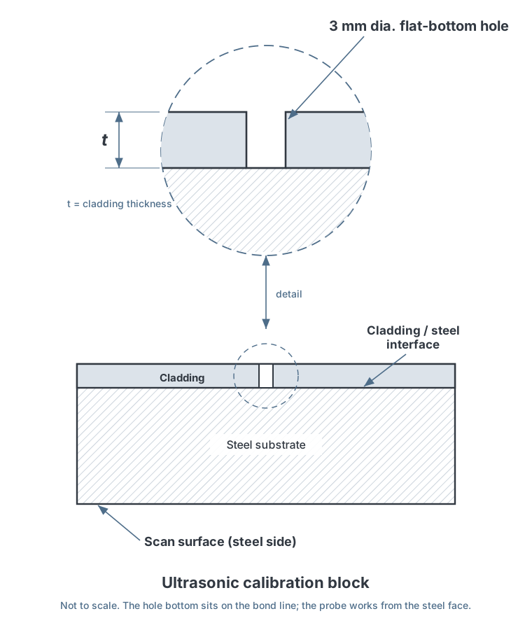
The calibration block sets the sensitivity of the ultrasonic examination. The flat bottom of the 3 mm hole lies on the cladding/steel interface, so it returns the echo of a known 3 mm reflector at exactly the depth of the bond line.
The block is scanned from the steel face, the same face the specimen is examined from, and the same calibration governs the examination before exposure and after it.
Two Ways to Supply the Specimen
A client can send finished specimens machined to the drawing, or send the clad plate and have TCR machine and fabricate them to the same drawing. Both routes end with the same specimen; the second moves the dimensional control, and the record of it, to the laboratory that runs the test.
- Client-prepared: specimens machined to the drawing, with the three pre-overlay measurements, the base and overlay material identities and the welding procedure for the side cladding.
- TCR-prepared: the clad plate or overlay coupon is sent, and the specimens and the calibration block are cut and machined to the drawing in TCR's machine shop, with the three dimensions measured and recorded before the side overlay is applied.
- Side cladding welded at TCR: the consumable and the welding procedure are agreed with the client in writing before fabrication starts.
- With either route: send the plate or overlay heat numbers, the bonding process and the post-weld heat treatment condition, because each of them is one of the variables the test ranks.
What the Enquiry Has to Specify
ASTM G146 covers a broad range of pressures, temperatures, cooling rates and hydrogen environments and does not fix one set of conditions. The exposure is set from the service the equipment will see, so the enquiry has to carry the numbers, and they are agreed in writing before the specimens go in.
- Hydrogen pressure at test temperature.
- Test temperature and hold time at temperature.
- Cooling rate after the hold, and the temperature it is controlled down to. This is the step that reproduces a unit shutdown.
- Number of exposure cycles.
- Base material, overlay or cladding material, bonding process and post-weld heat treatment condition.
- The acceptance limit on disbonded area, if the specification sets one.
How Disbonding Is Measured and Reported
Disbonding is read ultrasonically at the bond line, from the steel face, against the 3 mm flat-bottom hole in the calibration block. The bond is examined before exposure to record its as-fabricated condition and again after it, so an indication that was already there is not reported as damage the test caused.
- Specimen identity, the three pre-overlay dimensions, and the material and bonding details as received.
- The exposure as run: hydrogen pressure, temperature, hold time, cooling rate and number of cycles.
- Ultrasonic calibration on the 3 mm flat-bottom hole and the scan of the bond line, with any disbonded area located and quantified.
- A metallographic section through the interface on request, on the metallurgical evaluation bench.
- An accreditation statement: ASTM G146 results are issued in a report separate from accredited results, as NABL policy requires for a test outside the scope.
Where HID Sits in the Sour-Service Programme
Hydrogen induced disbonding belongs to the hot, high-pressure end of a refinery; the wet hydrogen sulphide mechanisms belong to the cold end. The same laboratory runs both, on the corrosion and sour service bench at Mahape.
- Sulphide stress cracking per NACE TM0177, hydrogen induced cracking per NACE TM0284, stress-oriented HIC per NACE TM0103 and four-point bend per NACE TM0316.
- CTOD with hydrogen sulphide pre-charging, on the fatigue and fracture toughness bench.
- HIC reference and control specimens manufactured in-house.
- Approved by Petroleum Development Oman and OQ Gas Networks, holder of the NACE International award for Excellent Laboratory in the Private Sector, with sour-service projects executed for Shell.
Related insights
2 published insights on this site bear directly on Hydrogen Induced Disbonding. They are below; the full index carries all 165 Materials Testing insights.
-
Hydrogen induced disbonding testing to ASTM G146 opens at Mahape, and why the overlay fails on the way down
TCR Engineering's Mahape laboratory is taking client specimens for hydrogen induced disbonding testing to ASTM G146. What the test reproduces, why…
-
Hydrogen induced disbonding is not cathodic disbondment: what ASTM G146 tests, and what it does not
Two tests share the word disbonding and almost nothing else. ASTM G146 is about stainless overlay on a reactor shell in hot hydrogen; cathodic…
Frequently asked questions
What does ASTM G146 test?
It evaluates whether the bond between a stainless alloy weld overlay or cladding and its steel substrate resists hydrogen induced disbonding in refinery high-pressure, high-temperature hydrogen service. A clad specimen is exposed to hydrogen at pressure and temperature, cooled at a controlled rate, and its bond line is examined ultrasonically for disbonding.
What specimen size does TCR need for HID testing?
A cylinder 73 ± 2 mm in diameter and 45 ± 2 mm thick, with a 6 ± 1 mm qualification cladding on one face and side cladding around the circumference. Thinner plate is tested at its own thickness. The diameter, the thickness and the cladding thickness are measured before the side overlay is welded.
Can TCR machine and prepare the HID specimens?
Yes. Send the clad plate or overlay coupon and TCR machines the specimens and the ultrasonic calibration block to the drawing in its machine shop, records the three pre-overlay dimensions, and agrees the side-cladding welding procedure with you in writing before fabrication.
Is ASTM G146 testing within TCR's NABL scope?
Not yet. TCR Engineering holds NABL certificate NABLT0726MH18640 with 1,483 accredited test items, and ASTM G146 is not among them today. HID results are issued in a separate report outside the accredited scope, and the report says so.
Which conditions does an HID enquiry have to specify?
Hydrogen pressure, test temperature, hold time, the cooling rate and the temperature it is controlled down to, the number of cycles, and the base, overlay, bonding process and post-weld heat treatment condition. ASTM G146 covers a broad range of each, so the exposure is set from the service the equipment will see.