+91 98335 30200  ·  sales@tcreng.com
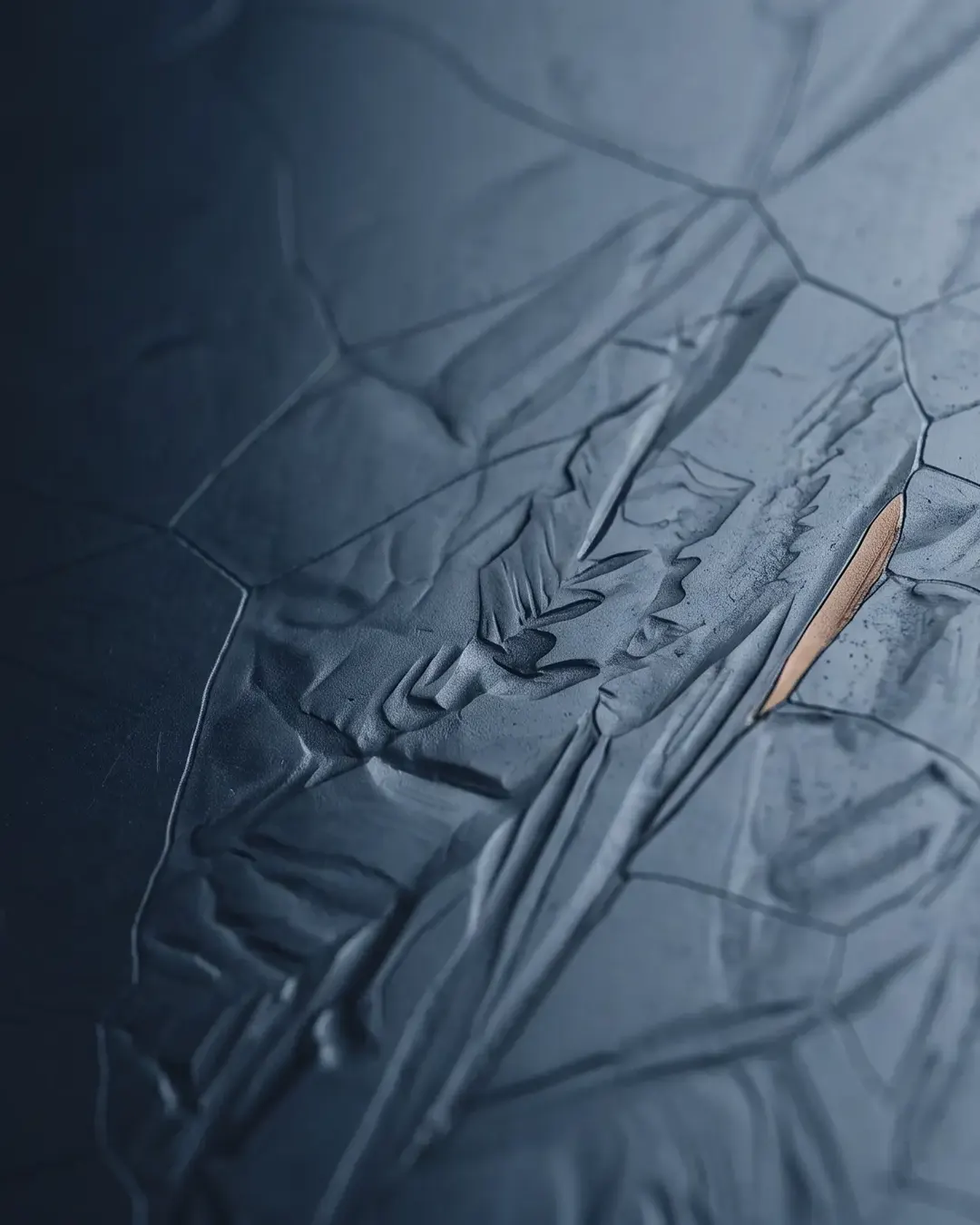
Extreme macro of a polished steel surface at a raking cold light, reading as texture and topography

Services · Materials Testing · Fatigue and Fracture Toughness

Fatigue and Fracture Toughness Testing per ASTM E1820, E399, E647 and E466

CTOD, J-integral, KIc, fatigue crack growth and S-N fatigue, pre-cracked and tested in-house on 50, 250 and 1,000 kN servo-hydraulic frames, reported under NABL NABLT0726MH18640.


Request a Quote

What this service covers

TCR Engineering, a NABL ISO/IEC 17025:2017 laboratory (NABLT0726MH18640) in Navi Mumbai, performs CTOD and J-integral fracture toughness testing per ASTM E1820, plane-strain KIc per ASTM E399, fatigue crack growth per ASTM E647 and axial fatigue per ASTM E466, with reports accepted in 90+ economies under the ILAC MRA.

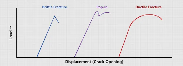
  • CTOD value and load versus crack opening displacement (COD) record per ASTM E1820, with in-house specimen pre-cracking.
  • Dedicated Fatigue Test Laboratory in Navi Mumbai: servo-hydraulic dynamic UTMs rated 50 kN, 250 kN and 1,000 kN, operating at 0.01 to 40 Hz.
  • Test temperatures from -20 °C to 1,100 °C across fracture toughness, FCGR, CTOD and J-integral methods.
  • Sour-service pedigree: PDO and OQGN approved; numerous projects executed for Shell.
  • NADCAP AC7101 Materials Testing accredited 2026 for aerospace verification testing.
  • Rail and rail-weld fatigue per RDSO IRS:T-29 and IRS:T-19, BS EN 14587-2 and ISO 14587; fatigue crack growth on rail steels per EN 13674.

What the tests measure

Fracture toughness testing measures a material's resistance to crack initiation and growth; fatigue testing measures its life under cyclic load. Together they underpin Engineering Critical Assessment of welds, damage-tolerant design in aerospace and rail, and material acceptance for offshore, pipeline and low-temperature service.

  • CTOD (crack tip opening displacement) quantifies crack-tip strain at the onset of crack growth, the governing measure for weld ECA per API 1104 Annex A.
  • J-integral and KIc characterise elastic-plastic and plane-strain fracture toughness for design and fitness-for-service input.
  • Fatigue crack growth rate (da/dN) per ASTM E647 feeds remaining-life calculation for cracked components.
  • S-N and strain-controlled fatigue per ASTM E466 and E606 establish endurance limits for components and welded joints.

Methods and standards

Each method below is performed at TCR Engineering's Navi Mumbai laboratory under NABL ISO/IEC 17025:2017 accreditation (NABLT0726MH18640) and cited in full on the test report. Where a client specification calls a different governing document, the report states the decision rule applied.

Fatigue and fracture toughness methods at TCR Engineering
MethodStandardScopeNotes
CTOD and J-integral fracture toughness ASTM E1820, ASTM E1290, ASTM B645; BS 7448 Parts 1 to 4; ISO 12135, ISO 15653 Pre-cracked CT and SENB specimens; CTOD value and load-COD record; span lengths 55 mm to 1,600 mm -20 °C to 1,100 °C
Plane-strain fracture toughness (KIc) ASTM E399; ISO 12737 Metallic materials; specimens 8 mm to 32 mm thickness across the temperature range, to 100 mm SENB at room temperature -20 °C to 1,100 °C; design and FFS input
Fatigue crack growth rate (da/dN vs ΔK) ASTM E647; ISO 12108 Metallic materials, including rail steels per EN 13674 -20 °C to 1,100 °C; feeds remaining-life calculation
R-curve determination ASTM E561 Crack-growth resistance curves
Force-controlled axial fatigue (S-N, HCF) ASTM E466 Components, fasteners, welded joints Ambient to 1,100 °C; constant amplitude
Strain-controlled fatigue (LCF) ASTM E606; ISO 12106 Low-cycle fatigue characterisation
Creep-fatigue interaction ASTM E2714 High-temperature cyclic duty
Rail and rail butt-weld fatigue RDSO IRS:T-29, IRS:T-19; BS EN 14587-2; ISO 14587; BS EN 13674-1 Four-point bending, 1,000 mm span, to 5 million cycles at 8.33 to 9.0 Hz on the 1,000 kN frame; three specimens drawn from eleven for statistical validation RDSO-governed work; fastenings per IRS T-31 and T-44
Rebar coupler static, slip, cyclic and fatigue IS 16172, ASTM A1034, IS 16651, ISO 15630, ISO 15835-2 Bar diameters 8 mm to 40 mm; LCF and HCF First BIS-accredited commercial laboratory in India for IS 16172
Grout fatigue CEB-FIP Model Code 1990/2010 Grouts for mechanical splices First laboratory in India for this test
Gully and manhole top fatigue BS EN 124-1, BS EN 124-5 Composite covers tested as complete units, up to 900 mm Includes permanent-set and load-bearing capacity tests
Helical spring static and fatigue RDSO and national/international standards Static load, spring rate, fatigue

Your challenge, our approach

Most fracture toughness enquiries arrive as a specification clause: an ECA requiring CTOD at a stated temperature, an aerospace programme requiring NADCAP-accredited verification, or a rail authority requiring IRS:T-29 fatigue. TCR reads the clause, states the decision rule, and reports against it, not around it.

  • Weld ECA per API 1104 Annex A Option 2: CTOD on weld metal and heat-affected zone, sampled per pipeline.
  • Low-temperature acceptance: CTOD in the cold chamber down to -20 °C.
  • Aerospace verification: NADCAP AC7101 Materials Testing (PRI certificate 29415245997, valid to 31 May 2027).
  • Sour-service fracture programmes alongside HIC and SSC testing under the corrosion pillar.

Case file

A servo-hydraulic fatigue frame at TCR Engineering running a cyclic test on a machined specimen
Servo-hydraulic fatigue and fracture toughness, to ASTM E466, E606 and E1820.

For Saudi Aramco's Jafurah gas compression plants (PWIS Package-1, 2024-2025), TCR performed Engineering Critical Assessment of 42-inch girth welds per API 1104 Annex A Option 2, running six CTOD tests per pipeline on pre-cracked specimens to set weld flaw-acceptance criteria.

Saudi Aramco · 2024-2025

Jafurah Gas Compression Plants ECA

ECA of 42-inch girth welds, PWIS Package-1, per API 1104 Annex A Option 2; six CTOD tests per pipeline.

Railways and steel

Rail-Track Fatigue Crack Growth

Fatigue crack growth testing of rail steels per EN 13674 for Jindal Steel & Power, and rail fatigue per IRS:T-29 for RDSO-governed programmes.

Aerospace and defence

Fracture-Toughness Programmes

Verification testing for HAL, MTAR Technologies, Vikram Sarabhai Space Centre and Navy and Defence fracture-toughness programmes, under NADCAP AC7101.

The Fatigue Test Laboratory

TCR Engineering runs a dedicated Fatigue Test Laboratory in Navi Mumbai built around servo-hydraulic dynamic universal testing machines rated 50 kN, 250 kN and 1,000 kN, operating from 0.01 to 40 Hz, with test temperatures from -20 °C to 1,100 °C. The in-house 50/250/1,000 kN fatigue-CTOD capability underpins the Engineering Critical Analysis programme for pipeline girth welds.

  • Specimens. 8 mm to 32 mm thickness across the full temperature range; 8 mm to 50 mm CT and SENB at room temperature; over 50 mm to 100 mm SENB; span lengths 55 mm to 1,600 mm.
  • Strain rates. High strain rate testing to 300 mm/s on the 50 kN frame and 100 mm/s on the 250 kN frame; slow strain rate to 10-7 mm/s.
  • Beyond metals. First laboratory in India for grout fatigue per CEB-FIP Model Code 1990/2010; gully and manhole top fatigue per BS EN 124-5 up to 900 mm covers; helical spring static and fatigue testing to RDSO standards.
  • Couplers. Static tensile, slip, cyclic tensile, fatigue, LCF and HCF testing of rebar couplers, 8 mm to 40 mm, per IS 16172, ASTM A1034, IS 16651, ISO 15630 and ISO 15835-2.
  • Full test spectrum. Fatigue crack propagation (da/dN vs ΔK), fracture mechanics (KIc, JIc, CTOD), three-point bend, spring fatigue, tension and compression, low- and high-cycle fatigue, and high-temperature tensile to 1,000 °C on the dynamic frames.

The complete capability record (Company Profile §4.10)

High-cycle fatigue testing at room and elevated temperatures per ASTM E466. Low-cycle fatigue per ASTM E606 Fatigue crack growth rate per ASTM E647. Fracture toughness: K1c per ASTM E399, J1c per ASTM E1820, CTOD per BS 7448 and ASTM E1820 (formerly ASTM E1290). Charpy impact transition curve development.

The in-house 50, 250 and 1000 kN Fatigue CTOD machine per ASTM E1820 underpins the Engineering Critical Analysis (ECA) programme for pipeline girth welds.

The first laboratory in India for grout fatigue per CEB-FIP Model Code 1990 / 2010. Manhole and gully top fatigue per BS EN 124-5 up to 900 mm covers municipal infrastructure clients.

Creep-fatigue interaction per ASTM E2714. Axial strain-controlled fatigue per ISO 12106 and fatigue crack growth per ISO 12108. Rail butt-weld uniaxial fatigue per BS EN 14587-2, IRS-T19, and ISO 14587.

Railway rail-weld fatigue per RDSO IRS:T-29 and IRS:T-19 runs to 5 million cycles at 8.33 to 9.0 Hz under four-point bending over a 1,000 mm span on the 1,000 kN dynamic frame, with three specimens drawn from eleven for statistical validation. High-tensile strand for prestressed bridge and high-speed-rail cable systems is tested per IS 14268, ASTM A416, ISO 10138, EN 10138-3, and ISO 15630-3, including 2 million-cycle fatigue at 70 percent of actual yield strength.

Multiple servo-hydraulic systems, rated 1000 kN, 50 kN and 250 kN, run from ambient to 1000 degrees Celsius and cover spring fatigue, three-point bend fatigue, and fatigue crack propagation (da/dN versus delta-K). High strain rate testing reaches 300 mm per second on the 50 kN frame and 100 mm per second on the 250 kN frame; slow strain rate testing runs to 10 to the minus 7 mm per second on the 100 kN frame.

Fatigue testing applies cyclic loading to a test specimen, to understand its performance under similar conditions when in actual use. The load application can either be a repeated application of fixed load or simulation of in-service loads. The load application may be repeated millions of times and up to several hundred times per second.

Many engineering metals and alloys display embrittlement at reduced (below sub-zero) temperatures. Structures fabricated from them fracture or shatter unexpectedly at low temperatures when loaded to stress levels at which performance would otherwise be satisfactory at room temperature. To avoid such incidents, selection of the right material can be done by testing them for their mechanical properties.

In the recent years, tremendous interest has been generated in fracture toughness testing based on linear elastic fracture mechanics. Fracture mechanics principles have been used to quantify safety factors in structural design, taking into account crack propagation and/or brittle fracture. Most structural members, components, vessels, piping, aviation, and aerospace are designed according to analysis criteria that guard against failure. CTOD testing requirement is most common in welded coupon as recommended in ONGC, EIL, DNV & API specification.

TCR Engineering has expanded its capabilities to include fatigue, fracture toughness, CTOD and high-temperature tensile testing with the addition of two fatigue systems with the Universal Testing Machine which has a capacity of 50 kN and 250 kN. The versatile Servo-hydraulic systems will allow the mechanical testing laboratory to perform numerous types of fatigue tests on different specimen sizes and orientations, in the temperature range from ambient to 1000° C. TCR has the capability of applying linear displacements, utilising linear and hydraulic actuators. Comparison fatigue testing of OEM and alternate source parts can also be performed to demonstrate equivalency of fatigue life.

Technical capabilities

TCR Engineering provides a diverse range of capabilities following ASTM/BS/ISO Specifications. Both ASTM E606 (Low-cycle fatigue, strain-controlled Fatigue Testing) and ASTM E466 (Load-controlled Fatigue Testing – High or Low-cycle fatigue testing) has been widely in use at TCR Engineering. Tests are also conducted for TMT RE-BAR, COUPLERS Fatigue test (100 Cycles test & 2 million Cycles test) as per IS 16172-2014.

TCR Engineering undertakes range of testing applications based out of its dedicated Fatigue Test Laboratory in Mumbai:

  • Fatigue Crack Propagation [da/dN vs ΔK Studies]
  • Fracture Mechanics [K1c, J1c, CTOD] Testing
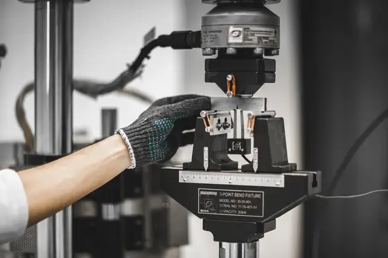
  • 3-Point Bend Testing of Materials
  • Spring Fatigue Testing
  • Room Temperature and High Temperature Tests [up to 1000 °C]
  • Tension/Compression
  • Low/High Cycle Fatigue (LCF/HCF) Testing
  • High Temperature Tensile Tests [up to 1000 °C]
  • High Strain Rate Testing [300mm/sec on 50KN and 100mm/sec on 250KN UTM]
  • Slow Strain Rate Testing [10-7 mm/sec on 50kN UTM]

Fracture Toughness Testing: Fracture toughness determines the amount of stress required to propagate an existing flaw or defect in specific materials. Since traditional methods of destructive testing cannot always predict how a material will behave during defect fracture, toughness is very important at the design stage

  • ASTM E1290: Standard Test Method for Crack-Tip Opening Displacement (CTOD) Fracture Toughness Measurement
  • ASTM E1820: Standard Test Method for Measurement of Fracture Toughness
  • ASTM E399: Standard Test Method for Linear-Elastic Plane-Strain Fracture Toughness KIc of Metallic Materials
  • Strain Fracture Toughness (KIC) for Metallic Materials
  • ASTM E647: Standard Test Method for Measurement of Fatigue Crack Growth Rates
  • BS 7448 (Part 1 to part 4) Fracture Mechanics Toughness tests. Method for Determination of KIc, Critical CTOD and Critical J Values of Welds in Metallic Materials

Crack-Tip Opening Displacement Testing: Crack-tip opening displacement is used as a type of fracture-toughness testing to determine if a material is appropriate for strenuous working conditions. CTOD testing is the measure of deformation, prior to failure in pre-cracked samples. This type of test is a variation of fatigue testing that has load rates more as representative of in-service conditions. TCR has capability to conduct the CTOD testing at temperature from ambient to -20 °C

Fatigue test standards (§4.10.1)

  • ASTM E466: Standard Practice for Conducting Force Controlled Constant Amplitude Axial Fatigue Tests of Metallic Materials
  • ASTM E606: Standard Practice for Strain-Controlled Fatigue Testing
  • ASTM E 2714 – Standard Test Method for Creep-Fatigue Testing
  • ISO 12106: Metallic materials — Fatigue testing — Axial-strain-controlled method
  • ISO 12108-2002 (E) – Metallic materials – Fatigue testing – Fatigue crack growth Method
  • IS16172-2014 Reinforcement Couplers for Mechanical Splices of Bars in Concrete- Specification
  • Uniaxial Fatigue Test as per BS EN 14587-2, IRS-T19, ISO 14587

Fatigue testing of butt-welded track rail (§4.10.2)

Fatigue testing of weld joints in rail tracks, as per IRS-T19, ISO 14587 & other National/International standards, is a crucial aspect of ensuring the safety and longevity of railway infrastructure. By following standardised testing procedures, rail industry professionals can gain valuable insights into the fatigue performance of weld joints, leading to improved design practices and enhanced reliability of rail tracks worldwide.

Fatigue testing involves subjecting the welded rail joint to repeated loading cycles that simulate the dynamic forces experienced during normal train operations. The purpose of this testing is to evaluate the performance of the welded joint under repeated stress and determine its ability to withstand the anticipated service conditions without failure or degradation over time.

Test Set-Up. A representative length of welded rail joint, usually several metres long (span length 1,000 mm), is selected for testing. The rail is typically mounted on a test fixture or a specialised fatigue testing machine that applies cyclic loading (4-point bend) to the joint. The loading can be applied in the form of vertical, forces, depending on the specific requirements as per relevant national/International standards.

Cycle Loading. The rail joint is subjected to repeated loading cycles that simulate the stress patterns encountered during train operations. The loading can vary in magnitude, frequency, and direction to simulate different operating conditions. The number of cycles applied during testing depends on the desired fatigue life assessment.

Monitoring and Measurements. During the fatigue test, various parameters are monitored and measured to assess the performance of the welded joint. These may include strain, displacement, crack propagation, and other relevant factors. Advanced measurement techniques such as strain gauges or non-destructive testing methods may be employed to gather accurate data.

Failure Criteria. The test is typically continued until a predefined failure criterion is reached. This criterion can be defined based on the appearance of cracks, changes in strain or displacement values, or other factors indicating potential failure or significant degradation of the welded joint.

Evaluation and Analysis. After the test, the collected data is analysed to determine the fatigue life and performance characteristics of the welded rail joint. This analysis helps in understanding the joint's ability to withstand cyclic loading and predict its service life in real-world operating conditions.

Standards and Regulations. Fatigue testing of butt-welded track rail is often conducted in accordance with specific industry standards and regulations. These standards provide guidelines for test procedures, acceptance criteria, and performance evaluation methodologies.

Applicable standards include RDSO IRS-T19, ISO 14587, BS EN 14587 Parts 1 and 2, and BS EN 13674-1, covering flash butt and other rail butt-welding processes. Track fastenings are covered by IRS T-31 (Elastic Rail Clips MK-V Type, ERC) and IRS T-44 (Insulating Liners RT-3506, GFN-66/HVN).

By performing fatigue testing on butt welded track rail, railway authorities and manufacturers can ensure that the rail joints are robust, reliable, and capable of withstanding the anticipated stresses and strains during the operational lifespan of the railway track. This testing helps enhance safety, reduce maintenance costs, and optimise the performance of rail systems.

Spectrum of services: the Dynamic UTM

At our fatigue testing division, we are equipped with an advanced Dynamic Universal Testing Machine (UTM) for conducting various fatigue tests. Our Dynamic UTM is designed to handle a wide range of testing requirements and can accommodate specimens of different sizes and strengths.

Here's a detailed overview of our testing machine and the comprehensive capabilities it offers. Dynamic UTM Specifications:

  • Capacity: Our Dynamic UTM boasts impressive load capacities, allowing us to conduct fatigue testing on a diverse range of materials and components. With load capacities of 50kN, 250kN, and 1000kN, we can effectively evaluate the fatigue behaviour of various specimens.
  • Frequency Range: Our Dynamic UTM operates within a frequency range of 0.01Hz to 40Hz, enabling us to simulate real-world loading conditions and accurately assess the fatigue performance of materials under dynamic loading.

In our fatigue testing division, we specialise in a range of fatigue testing methodologies, including:

Fracture Toughness (KIC) Test (§4.10.3)

  • Specimen Size: We can test specimens ranging from 8mm to 32mm in thickness on Test temperature range: at subzero up to -20 °C & at elevated temperature up to 1100 °C. We can test specimens ranging from 8mm to 50mm (CT/SENB specimen) at Room Temperature & over 50 mm to 100mm (SENB specimen only, depends on the strength of material)
  • Test Method: Our testing procedures adhere to recognized industry standards such as ASTM E399, ASTM E1820, ASTM B645, BS7448 (Part 1-4), ISO12135, ISO 12737 and ISO15653, ensuring accurate and reliable results.
  • Test temperature range: -20°C to 1100°C

Fatigue Crack Growth Rate (FCGR) Test (§4.10.4)

  • Specimen Size: We can test specimens ranging from 8mm to 32mm in thickness on Test temperature range: at subzero up to -20 °C & at elevated temperature up to 1100 °C. We can test specimens ranging from 8mm to 50mm (CT/SENB specimen) at Room Temperature & over 50 mm to 100mm (SENB specimen only, depends on the strength of material)
  • Test Method: Our testing protocols strictly follow ASTM E647, ISO 12108 guidelines, allowing us to assess the crack growth behaviour under fatigue loading accurately.
  • Test temperature range: -20°C to 1100°C

CTOD Test (§4.10.5)

  • Specimen Size: We can test specimens ranging from 8mm to 32mm in thickness on Test temperature range: at subzero up to -20 °C & at elevated temperature up to 1100 °C. We can test specimens ranging from 8mm to 50mm (CT/SENB specimen) at Room Temperature & over 50 mm to 100mm (SENB specimen only, depends on the strength of material)
  • Span Length: Our testing equipment accommodates span lengths between 55mm and 1,600mm.
  • Test Method: We adhere to industry standards such as ASTM E1290, ASTM E1820, BS7448 (Part 1-4), ISO12135, and ISO15653, ensuring precise CTOD measurements.
  • Test temperature range: -20°C to 1100°C

J-Integral (JIC) Test (§4.10.6)

  • Specimen Size: We can test specimens ranging from 8mm to 32mm in thickness on Test temperature range: at subzero up to -20 °C & at elevated temperature up to 1100 °C. We can test specimens ranging from 8mm to 50mm (CT/SENB specimen) at Room Temperature & over 50 mm to 100mm (SENB specimen only, depends on the strength of material)
  • Test Method: We follow standardised test methods, including ASTM E1820, ASTM B645, BS7448 (Part 1-4), ISO12135, and ISO15653, to accurately determine the J-Integral values.
  • Test temperature range: -20°C to 1100°C

Uni-axial Fatigue Test (§4.10.7)

  • Test Method: Our fatigue testing procedures align with ASTM E466, ASTM E606, and IS 5074, IS 16172 guidelines, ensuring comprehensive assessment of uni-axial fatigue behaviour.
  • Test temperature range: ambient to 1100°C

Helical Spring Test (§4.10.8)

  • Static Load Test.
  • Load v/s Displacement (Spring Constant/ Spring Rate)
  • Fatigue Test

Additionally, our capabilities extend beyond traditional fatigue testing, as we offer specialised testing for Reinforcement Couplers and Grouter for Mechanical Splices of Bars in Concrete. Our testing services in this area include:

  • Static Tensile Test
  • Slip Test
  • Cyclic Tensile Test
  • Fatigue Test
  • Low Cycle Fatigue Test
  • High Cycle Fatigue Test

We can accommodate reinforced bars with nominal diameters ranging from 8mm to 40mm, adhering to relevant industry standards such as IS16172, ASTM A1034, IS16651, ISO15630, and ISO15835-2. With our Dynamic UTM and comprehensive range of testing capabilities, we are well-equipped to meet your fatigue testing needs, providing accurate and reliable results for a wide range of materials.

Fatigue testing of gully and manhole tops made of composite materials (§4.10.9)

Test as per BS EN BS EN 124-1 and BS EN 124-5

At TCR, we understand the critical importance of ensuring the durability, reliability, and safety of infrastructure components like gully and manhole tops, especially when constructed from advanced composite materials. Fatigue testing simulates real-world conditions and repetitive stresses that gully and manhole tops may experience over their operational lifetimes. By subjecting these components to fatigue testing, manufacturers and users can assess how well the materials and structures withstand cyclic loading without developing cracks or failures. This ensures the products' long-term reliability and helps in predicting their lifespan.

Gully and manhole tops are critical components of infrastructure, often subjected to heavy loads, traffic, and environmental stresses. Fatigue testing helps identify potential weaknesses or fatigue-related failure modes that could compromise structural integrity and safety over time. Addressing these issues early through testing minimises the risk of sudden failures, ensuring safer operation and maintenance of infrastructure.

Gully and manhole tops are fatigue tested as complete units in their intended position of use where cover/grating is suitably positioned within the frame and the frame is supported in a manner to replicate intended installation support structure. TCR’s facilities and expertise thoroughly evaluates against the rigorous requirements outlined in BS EN 124-1 (for gully tops) and BS EN 124-5 (for manhole tops) with rectangular / circular / triangular as well as double or multiple triangular covers and/or gratings.

TCR’s testing protocols cover a comprehensive range of performance factors, including load-bearing capacity, impact resistance, chemical resistance, and fatigue durability. TCR's fracture mechanics department has specialised testing machine (complying to EN ISO 7500-1:2004) which includes a Servo Hydraulic Dynamic UTM machine which is capable of applying a load as recommended (at least 25 % greater) than the respective test load (FT) for classes A 15 to D 400 and (at least 10 % greater than) the respective test load (FT) for classes E 600 and F 900.

Conducting fatigue testing as part of quality control processes ensures that manufactured gully and manhole tops meet design specifications and performance expectations. It helps manufacturers identify potential design flaws, material weaknesses, or manufacturing defects that could lead to premature failures in the field, thereby improving overall product quality and customer satisfaction.

TCR also specialises in conducting both the Permanent Set Test and Load Bearing Capacity Test to evaluate material performance. The Permanent Set Test is undertaken to evaluate a material's resilience by measuring its ability to recover its original shape after being subjected to a specified load over a defined period. Additionally, TCR conducts the Load Bearing Capacity Test to determine the maximum load a material or structure can endure before failure. This test provides crucial insights into the strength and durability of metals, polymers, composites, and other materials, supporting informed engineering and design decisions with precise data.

Whether you're a manufacturer seeking compliance validation or Kitemark certification, or a specifier ensuring product suitability, our dedicated team of experts is here to support you every step of the way. By partnering with us, you can be confident that your composite gully and manhole tops will undergo detailed testing processes.

Standards: ASTM E466 (high-cycle fatigue), ASTM E606 (low-cycle fatigue), ASTM E647 (fatigue crack growth), ASTM E399 (K1c), ASTM E1820 (J1c and CTOD), ASTM E561 (R-curve), ASTM E2714 (creep-fatigue). BS 7448 (CTOD). ISO 12106 and ISO 12108. API 5L3 (drop-weight tear). BS EN 124-5 and BS EN 14587-2 (infrastructure and rail fatigue).

Fracture toughness rarely travels alone: sour-service programmes pair CTOD with HIC and SSC testing, high-temperature plant pairs it with creep, and every fracture number feeds Engineering Critical Assessment under the asset integrity pillar.

Related insights

15 of the 135 published insights tagged to Materials Testing bear directly on Fatigue and Fracture Toughness. The 6 most relevant are below.

Read all 135 Materials Testing insights →All insights →

Frequently asked questions

Which standards govern fatigue and fracture toughness testing at TCR Engineering?

CTOD and J-integral per ASTM E1820, with BS 7448, ISO 12135 and ISO 15653 where specified; KIc per ASTM E399; fatigue crack growth per ASTM E647; axial fatigue per ASTM E466; strain-controlled fatigue per ASTM E606; and rail fatigue per IRS:T-29 and EN 13674.

What temperature range can TCR test at?

Fracture toughness, FCGR, CTOD and J-integral testing runs from -20 °C to 1,100 °C, with specimen pre-cracking carried out in-house before the toughness test. Uniaxial fatigue runs from ambient to 1,100 °C.

Does TCR test CTOD for sour-service and pipeline projects?

Yes. TCR is PDO and OQGN approved and has executed numerous projects for Shell. For Saudi Aramco's Jafurah gas compression plants (2024-2025), TCR performed ECA of 42-inch girth welds per API 1104 Annex A Option 2, with six CTOD tests per pipeline.

Are TCR's fracture toughness reports accepted outside India?

Yes. NABL is an ILAC MRA signatory, so TCR reports under NABLT0726MH18640 are accepted in 90+ economies by reciprocal bodies including A2LA, UKAS, DAkkS and Cofrac. Samples are received from 15+ countries.

Which industries use TCR's fatigue and fracture toughness testing?

Pipelines (ECA per API 1104), aerospace and defence (NADCAP AC7101 Materials Testing accredited 2026; programmes for HAL, MTAR Technologies, Vikram Sarabhai Space Centre and the Navy), railways (rail-track fatigue crack growth per EN 13674 and fatigue per IRS:T-29 for Jindal Steel & Power and RDSO-governed work), marine and offshore, and power generation.

Which industries use this testing?

Pipelines (ECA per API 1104), aerospace and defence (NADCAP AC7101), railways (EN 13674, IRS:T-29), marine and offshore, and power generation.

Know the crack-driving force before the crack finds it.

Request a Quote