
Services · Asset Integrity and Engineering Consulting
Shaft and Rotating Component Failure Analysis
A broken shaft carries the record of how it broke on its own fracture surface. The origin is readable, and it is usually not where the load was.
Request a QuoteOverview
TCR Engineering Services Pvt. Ltd., a NABL ISO/IEC 17025:2017 accredited laboratory in Navi Mumbai (certificate NABLT0726MH18640), investigates failed shafts, rotors, gears, couplings and other rotating components. The work reads the fracture surface first, then the microstructure, the hardness, the chemistry and the design, and it draws on a group archive of 9,000+ documented failure investigations.
What a Shaft Fracture Surface Tells You
Most failed shafts fail by fatigue, and a fatigue fracture is a dated record of the event. The origin, the direction of crack growth, the number of initiation sites and the size of the final fast-fracture zone are all read from the surface before a single specimen is cut, which is why the fracture faces must not be cleaned, fitted back together or wire-brushed before they reach a laboratory.
- The origin: a single origin points at a stress raiser, a keyway, a fillet, a nick or a hard spot. Multiple origins around the circumference point at a nominal stress that was simply too high.
- Ratchet marks: the steps between adjacent origins. Their number counts the initiation sites, and a row of them says the stress concentration was severe.
- Beach marks: the macroscopic arrest lines. Their curvature says whether the loading was rotating-bending, reversed bending, torsion or a combination, and their spacing says whether the load varied.
- The final fast-fracture zone: its area against the section is a direct measure of how highly stressed the shaft was. A small final zone means a low nominal stress and a long crack life; a large one means the shaft was working near its limit.
- Striations under the SEM: the cycle-by-cycle record, which confirms fatigue and, where the spacing is measurable, bounds the growth rate.
A torsional fatigue crack runs at roughly 45 degrees to the axis and a rotating-bending crack runs normal to it. That single observation separates a drive-train problem from a bearing or alignment problem before any test is run.
The Damage Mechanisms We Separate
Naming the mechanism is the whole job. A shaft that failed by corrosion fatigue and a shaft that failed by plain fatigue call for different corrective action, and the difference is visible only in the evidence.
| Mechanism | What it looks like | What it usually means |
|---|---|---|
| Rotating-bending fatigue | Crack normal to the axis, beach marks concave towards the origin | Misalignment, an unbalanced rotor, or a fillet radius below drawing |
| Torsional fatigue | Crack at 45 degrees to the axis, often a star or spiral pattern | Cyclic torque, a drive-train resonance, or shock loading |
| Corrosion fatigue | Multiple origins, corrosion product in the crack, no clear single site | The environment, not the load, set the initiation life |
| Fretting fatigue | Initiation under a shrink fit, coupling hub or bearing seat, with red or black debris | Micro-movement at an interface that was assumed to be rigid |
| Stress corrosion cracking | Branched, largely brittle cracking with little section loss | A susceptible alloy, a tensile stress and a specific environment |
| Hydrogen embrittlement | Intergranular fracture, often delayed, frequently near a plated surface | Hydrogen from plating, pickling, welding or cathodic protection |
| Overload and single-cycle fracture | Shear lips and dimpled rupture, or cleavage in a brittle material | A load event outside design, or a material below specification |
| Creep and thermal fatigue | Cavitation on grain boundaries, or a network of surface cracks | Service above the temperature the material was chosen for |
Where the evidence supports more than one mechanism, the report says so and states what further evidence would separate them. A single named cause that the evidence does not carry is worth less than an honest short list.
The Investigation, Step by Step
The sequence is fixed and it is non-destructive first, because every later step consumes evidence. Nothing is sectioned until the fracture surface has been photographed, documented and, where the case may be argued later, preserved.
- 1. Background and duty. Service history, running hours, the load and speed spectrum, the material specification, the drawing, and what changed before the failure.
- 2. As-received and macro examination. Dimensional check against the drawing, photography under raking light, and the fractographic read described above. Fillet radii and surface finish are measured, because the stress raiser is often on the drawing.
- 3. Scanning electron microscopy and EDS. Fracture mode, striations, dimples, cleavage or intergranular facets, and the elemental composition of any corrosion product, deposit or inclusion at the origin.
- 4. Metallography. Preparation and etching to ASTM E3 and E407, grain size to ASTM E112, inclusion content to ASTM E45, and case depth or decarburisation where the shaft is surface-hardened.
- 5. Hardness. A traverse rather than a single reading, to ASTM E10, E18 or E384, which is what exposes a soft core, an unintended surface layer or a heat-treatment miss.
- 6. Chemical analysis. Optical emission and combustion analysis to ASTM E415 and ASTM E1019, read against the specification the shaft was bought to, not against a general expectation.
- 7. Mechanical properties. Tensile to ASTM E8/E8M and impact to ASTM E23 on material taken away from the damage, where enough section survives.
- 8. Synthesis. Mechanism, root cause, contributing factors and recommendations, each traced to a specific observation.
Chemical analysis, mechanical testing, metallography and hardness are performed under the NABL ISO/IEC 17025:2017 scope of certificate NABLT0726MH18640, which carries 1,483 accredited test items. The investigation that draws them together is an engineering opinion and is signed as one.
Where the Answer Has to Survive Scrutiny
A shaft failure report is rarely read only by the plant. It goes to an insurer, to the original equipment manufacturer, to a contractor whose workmanship is in question, and sometimes to a court. It is written to hold up in all four.
- Insurance and warranty claims: the mechanism and the timeline decide liability, and both come off the fracture surface.
- Referee and third-party appointments: where a supplier and a purchaser disagree, an accredited independent laboratory with no commercial interest in either answer is the route out.
- Repeat-failure investigations: the second failure of the same component is a design or a duty problem, and the two fracture surfaces compared side by side usually say which.
- Fleet decisions: one failed shaft raises the question of the others. In-situ metallographic replication lets the surviving units be read without being taken out of service.
Where a failure points at a wider population, the investigation hands over to remaining life assessment or to fitness-for-service to API 579-1/ASME FFS-1, so the decision about the rest of the fleet rests on the same evidence.
Related insights
6 published insights on this site bear directly on Shaft Failure Analysis. They are below; the full index carries all 92 Asset Integrity insights.
-
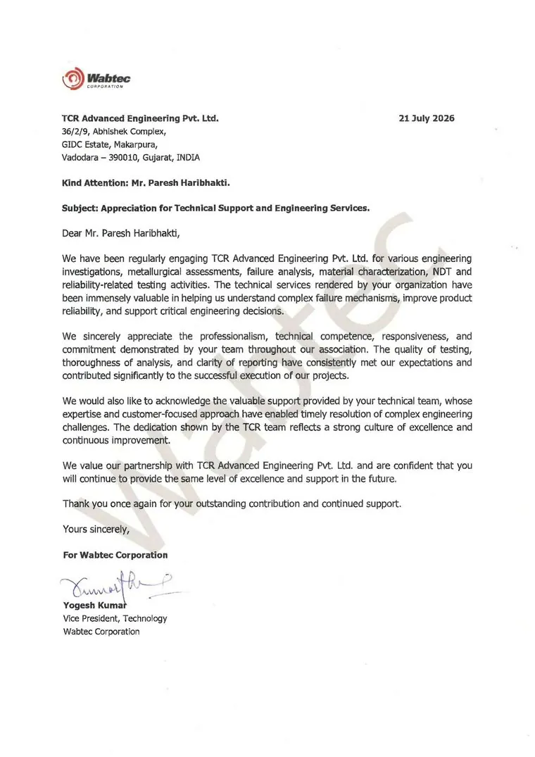
Wabtec Corporation Writes to TCR Advanced: Failure Analysis, Material Characterisation and Reliability Testing
Wabtec Corporation has written to TCR Advanced Engineering to record its appreciation for engineering investigations, metallurgical assessments,…
-
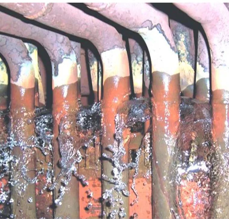
Boiler Tube Failure Analysis
Boiler tube failure analysis reveals the metallurgical evidence behind costly power plant outages and provides proven solutions to prevent recurrence.
-
Boiler Tube Failure Analysis: A Complete Investigation Guide for Power Plants
A complete guide to boiler tube failure investigation: the waterside, fireside, temperature and mechanical damage mechanisms, and how each is proved.
-
Why Failure Analysis Metallurgical Laboratory India Services Prevent Million-Dollar Disasters
Failure analysis metallurgical laboratory India prevents million-dollar disasters. TCR Engineering's 50+ years expertise identifies root causes.
-
Hindalco Commends TCR for Failure Analysis Expertise
TCR Advanced delivers expert metallurgical analysis for Hindalco cranes, ensuring safety, efficiency, and reliability in critical operation
-
Failure Analysis project from Adani Power Plant
Boiler tube failure at the 5x660 MW Tiroda Thermal Power Plant in Gondia

Frequently asked questions
How do you tell a fatigue failure from an overload failure on a shaft?
By the fracture surface. Fatigue leaves beach marks, ratchet marks and a distinct final fast-fracture zone, and under the SEM it leaves striations. An overload failure leaves shear lips and dimpled rupture across the whole section with no arrest marks. The two are separated before any specimen is cut.
Should the two halves of a broken shaft be fitted back together before sending them?
No. Fitting the halves together rubs the fracture faces against each other and destroys the origin, which is the single most informative area on the component. Pack the two halves separately, protect the fracture faces from contact and from moisture, and do not clean, wire-brush or degrease them.
What material and history do you need with the shaft?
The material specification and any mill certificate, the drawing with fillet radii and surface finish, running hours, the load and speed duty, the date and circumstances of the failure, and anything that changed before it. Where those are not available the investigation still runs; it simply carries wider bounds, and the report says so.
Is failure analysis covered by TCR's NABL accreditation?
The individual test methods are. Chemical analysis, mechanical testing, metallography and hardness are performed under NABL certificate NABLT0726MH18640, which carries 1,483 accredited test items. The investigation that draws those results into a cause is an engineering opinion, signed as one, and no accreditation body accredits an opinion.
How long does a shaft failure investigation take?
It depends on how much of the sequence the case needs and on whether long duration tests are called for. The fractographic and metallurgical work that answers most cases is a matter of days, not weeks. Where a plant is down, say so when the sample is booked and the sequence is ordered to give the operational answer first and the full report after.
Can you examine the other shafts without taking them out of service?
Yes. In-situ metallographic replication to ASTM E1351 reads the microstructure of a component in place, with no cutting and no sample removal. TCR has taken more than 100,000 in-situ replicas and fields 12 in-situ metallographic teams across the group.